


Adjustment
12 - 31
12.
05.10
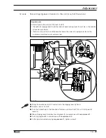
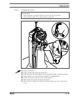
Scissor return lever
Requirement
When the roller of tripping lever
3
is exactly at the point of the trip of control cam
2
the
maximum distance between the roller of return lever
4
and control cam
2
must be
0.2 mm.
●
Loosen screw
1
.
●
Bring the needle bar to BDC and activate the engaging lever by hand.
●
Position the point of the trip of control cam
2
exactly at the middle of the roller of tripping
lever
3
by turning the handwheel in the direction of sewing.
●
Maintaining this position, bring the return lever
4
to rest against the side of tripping
lever
3
and turn it radially in accordance with the
requirement
.
●
Tighten screw
1
.
3
1
4
2
Fig. 12 - 27
2
4
max. 0.2 mm
Содержание 3734-2/01
Страница 73: ...Adjustment 12 39 Fig 12 34 4 5 2 mm ...


