


Adjustment
12 - 27
12.
05.06
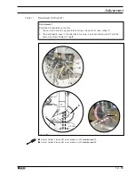
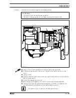
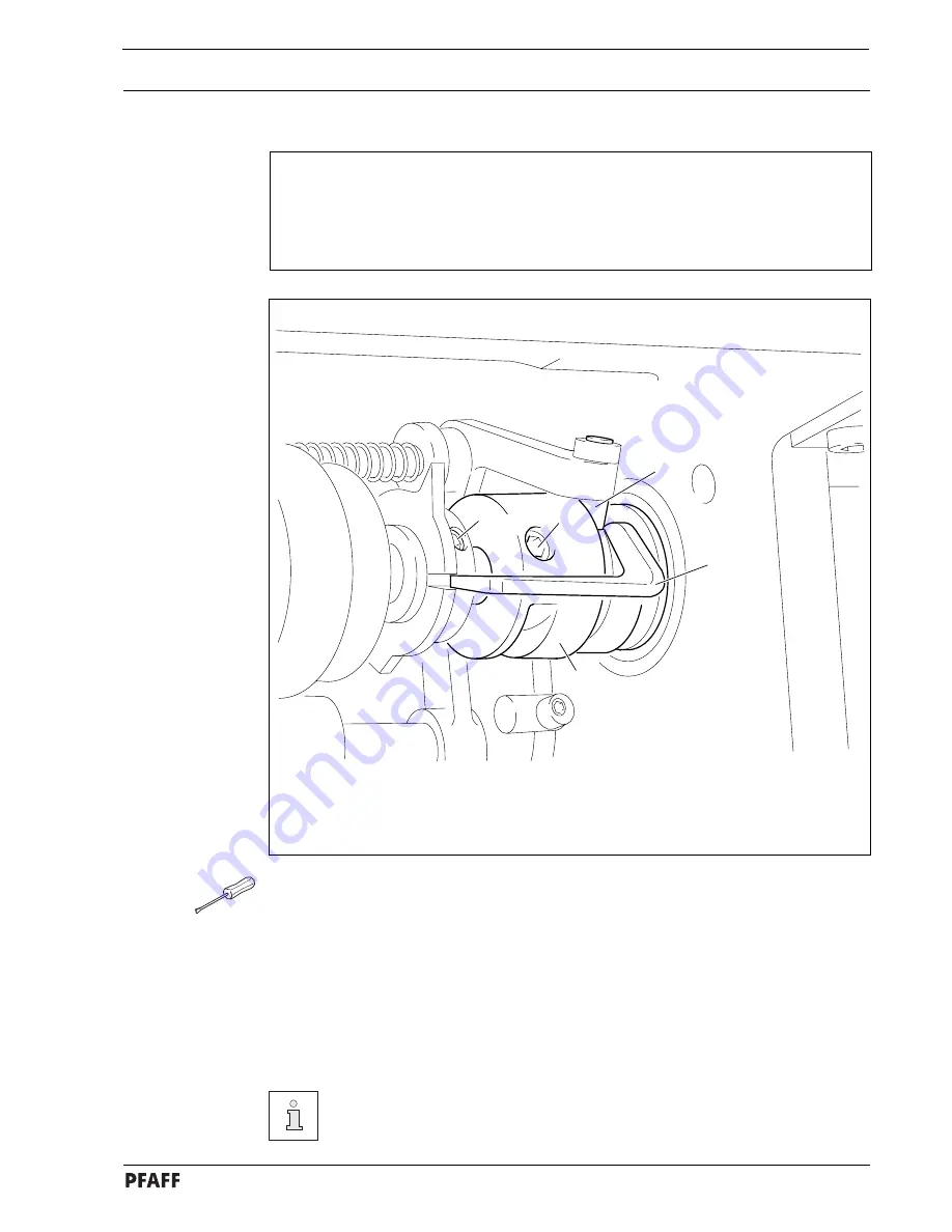
Control cams to the bobbin opener and cutter
( adjustment with adjustment gauge )
Requirements
With the needle bar at BDC, both control cams must be positioned in such a way that
1. adjustment gauge
5
can be slid into the grooves of both control cams,
2. both cams are on the rests of adjustment gauge
5
and
3. the bent section of adjustment gauge
5
is touching roller
3.
1
2
4
5
3
Fig. 12 - 23
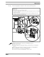
●
Loosen screws
1
and
2.
●
Bring the needle bar to BDC and activate the tripping lever by hand ( roller
3
engaged ).
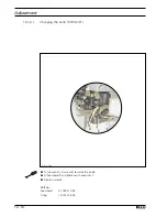
●
Adjust the control cams in accordance with the
requirement
and insert adjustment
gauge
5
.
●
Turn control curve
4
in accordance with the
requirement.
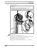
●
Taking care to ensure that control cam
4
is touching the bearing collar, tighten the
accessible screws
1
and
2
.
●
Remove adjustment gauge
5
and tighten the remaining screws
1
and
2
.
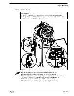
For adjustment without the gauge see chapter
12.05.07 Radial position of the
control cam in relation to the bobbin opener
and
chapter 12.05.08 Control
cam in relation to scissor.
Содержание 3734-2/01
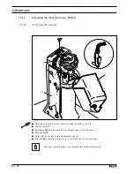
Страница 73: ...Adjustment 12 39 Fig 12 34 4 5 2 mm ...


