Pfaff 3519-4/01 Скачать руководство пользователя страница 78

Adjustment

78

13

.06.02 

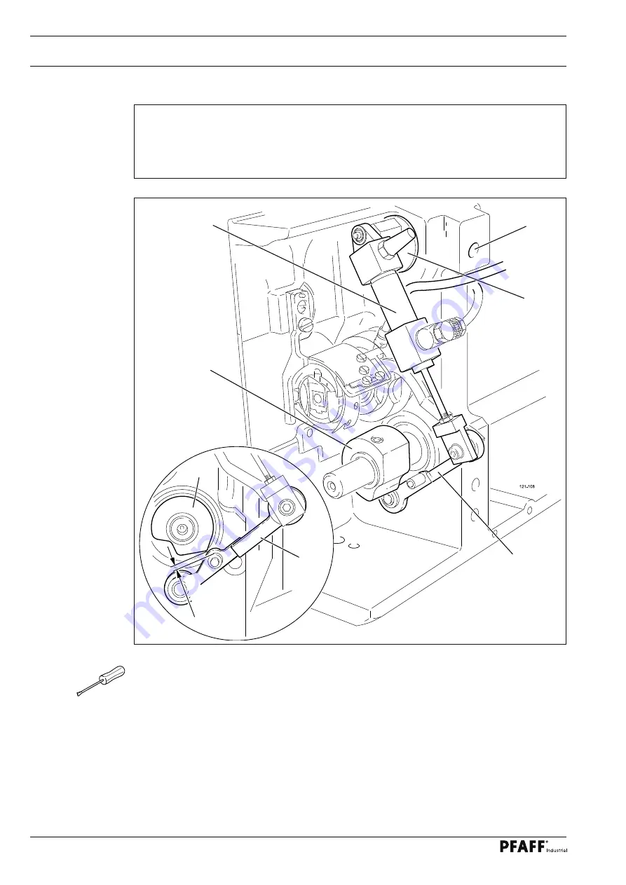
Adjusting the roller lever

Requirement

When cylinder 

1. 

is fully extended, the roller of roller lever 

should be 

0.1 mm

 away 

from the highest point of control cam 

5.

Cylinder 

2. 

should be parallel to the front edge of the bed-plate.

Adjust or turn eccentric 


(screw 

2) 

in accordance with the 

requirements

.

50-65a

5

4

0,1 mm

Fig. 13 - 11

5

3

1

2

4

Содержание 3519-4/01

Страница 1: ...INSTRUCTION MANUAL 3519 4 01 296 12 18 635 002 Betriebsanleitung engl 03 11 This instruction manual applies to machines from serial number 2 763 205 and software version 0361 013 onwards...

Страница 2: ...of PFAFF Instruction Manuals whether in whole or in part is only permitted with our previous authorization and with written reference to the source PFAFF Industriesysteme und Maschinen AG Hans Geiger...

Страница 3: ...king materials 14 5 04 Storage 14 6 Explanation of symbols 15 7 Controls 16 7 01 On off switch 16 7 02 Machine control unit button 16 7 03 Switch for the extractor fan optional 17 7 04 Emergency off b...

Страница 4: ...operation 40 10 03 Manual sewing mode 41 10 04 Error messages 43 11 Input 44 11 01 Overview of the functions in the input mode 44 11 02 Creating altering seam programs 46 11 02 01 Creating altering si...

Страница 5: ...ming check 82 13 06 07 Readjusting the control cam 83 13 07 Adjusting the loading table 84 13 07 01 Basic setting of the loading table height 84 13 07 02 Positioning the loading table 85 13 07 03 Retr...

Страница 6: ...ettings 117 13 25 01 Selecting and altering parameters 117 13 25 02 Parameter list 118 14 Control unit 120 14 01 Basic setting Diagnosis Pin assignment 120 14 01 01 Power unit A30 120 14 01 02 Basic c...

Страница 7: ...hine unattended and during maintenance work the machine is to be separated from the power supply by switching off the On Off switch or by removing the plug from the mains Everyday maintenance work is...

Страница 8: ...ant points for the user This Instruction Manual is an integral part of the machine and must be available to the operating personnel at all times The Instruction Manual must be read before operating th...

Страница 9: ...es in the machine which may limit its safety 1 05 02 Specialist personnel Specialist personnel are persons with a specialist education in the fields of electrics electro nics and mechanics They are re...

Страница 10: ...es and loading equipment Never leave objects on the table while adjusting the machine settings Objects can become trapped or be slung away Danger of injury Do not look into laser beam either with or w...

Страница 11: ...this machine which have not been approved of by the manufacturer are considered to be inappropriate The manufacturer cannot be held liable for any damage caused by the inappropriate use of the machine...

Страница 12: ...ches 1 9 Sewing area size Dart depth 5 12 mm Dart length 80 395 mm Max material thickness for sewing 4 mm Machine dimensions Length approx 2 800 mm Width 1 200 1 800 mm Height approx 1400 mm Weight ap...

Страница 13: ...d various plastic materials The electrical equipment comprises plastic materials and copper The machine is to be disposed of according to the locally valid pollution control regula ti ons if necessary...

Страница 14: ...e machines are only transported in an upright position 5 03 Disposal of packing materials The packing materials of this machine comprise paper cardboard and VCE fibre Proper dis posal of the packing m...

Страница 15: ...struction manual work to be carried out or important information is accentuated by symbols These symbols have the following meanings Note information Cleaning care Lubrication Maintenance repairs adju...

Страница 16: ...ch 1 1 Fig 7 02 7 02 Machine control unit button After the power supply has been swit ched on with the main switch see Chap ter 7 01 Main Switch press button 1 to switch on the machine control unit an...

Страница 17: ...o switch off the extractor fan Fig 7 03 1 2 7 04 Emergency off button In the event of emergencies press the emergency off button 1 to stop the ma chine immediately The emergency off button 1 may only...

Страница 18: ...ted by pressing the appropriate po sition on the monitor By pressing the cor responding function this is carried out or switched on or off immediately or a further menu appears e g for entering a valu...

Страница 19: ...er the sewing cycle has been completed the illuminated start keys 1 indica te that the next sewing cycle can be started If the threading aid is activated by pressing both start keys 1 at the same time...

Страница 20: ...ly of electricity and compressed air must be available at the machine site see Chapter 3 Specifications It must also be ensured that the standing surface of the machine site is firm and horizontal and...

Страница 21: ...Detaching the transit lock on the loading table Remove screw 1 Loosen screw 2 and remove bracket 3 Re tighten screw 2 Fig 8 02 1 2 3 8 01 03 Detaching the transit lock on the sewing head Remove screws...

Страница 22: ...Installation and commissioning 22 8 01 04 Detaching the transit lock on the loading clamp Open cover 1 Remove screws 1 Close 1 cover 1 Fig 8 04 1 2 2...

Страница 23: ...tand into the hole on the machine stand and fasten it with the enclosed nuts 8 01 05 Connecting the pedal Insert plug 1 in the corresponding socket on the machine stand Secure the plug connection with...

Страница 24: ...es for any damage Have a qualified person check whether the motor can be driven with the existing power voltage If there are any differences the machine must definitely not be operated The machine mus...

Страница 25: ...ch Carry out a test run see Chapter 10 Sewing Switching off the machine Switch off the main switch Explanation of the other functions on the display Input menu This function is used to call up the inp...

Страница 26: ...l Switch on the machine Call up the input mode Select the service menu Select control panel functions Change the display contrast Switch the key tone off or on Never reduce the display contrast to the...

Страница 27: ...e machine into its basic position 9 Preparation All regulations and instructions in this Instruction Manual are to be observed Special attention is to be paid to the safety regulations All preparation...

Страница 28: ...up the threading aid The feed bar moves out of the needle area the sewing foot is lowered and the sewing start function is locked Thread the machine as shown in Fig 9 02 Adjust the needle thread tens...

Страница 29: ...anti clockwise direction Switch on the bobbin winder by pressing bobbin winder spindle 2 and lever 3 simultane ously The bobbin fills up during sewing To adjust the bobbin winder tension turn knurled...

Страница 30: ...h 1 and take out bobbin case 2 together with the bobbin Insert the filled bobbin in the bobbin case as shown in the above illustration when the thread is drawn the bobbin should turn in the direction...

Страница 31: ...31 9 05 Changing the dart insert Fig 9 05 Screw the enclosed pin 1 into the threaded hole in insert 2 Pull out insert 2 Fit new insert to match the dart depth Insert blind insert 3 for double pointed...

Страница 32: ...Preparation 32 9 06 Adjusting the loading unit for ironing compensation strips Fig 9 06 Loosen screw 1 Adjust the loading unit for ironing compensation strips to match the dart length 1...

Страница 33: ...9 double pointed darts Program numbers 300 399 tapered darts Confirm the selection and quit the selection menu Description of the other functions Clear This function sets the value at 0 Arrow keys The...

Страница 34: ...n the machine Call up the menu for entering the program number Call up the menu for entering the group number Select the desired group number Confirm the selection and quit the selection menu Descript...

Страница 35: ...ion menu see 9 08 01 Selecting a program group Select the group programming function Configure the program group from existing seam programs by entering the program numbers on the number block The cur...

Страница 36: ...e status all relevant functions and settings for the production are shown on the display Automatic ope ration is standard but it is possible to switch to manual operation when setting up and checking...

Страница 37: ...positioning tube Workpieces with a striped or checked pattern can be aligned with the aid of a la ser beam Do not look into laser beam either with or without optical equipment Danger of injury to the...

Страница 38: ...Sewing 38 Double pointed darts Fig 10 02 0 320 mm 0 320 mm Insertion marking Insertion marking...

Страница 39: ...Sewing 39 10 01 02 Insert the workpiece using the loading table Double pointed darts Fig 10 03 0 320 mm 0 320 mm Insertion marking Insertion marking...

Страница 40: ...g the program number see Chapter 9 07 Selec ting the program number Input menu This function is used to call up the input mode see Chapter 11 Input Program selection Each of these functions is used to...

Страница 41: ...le Basic position This function is used to bring the machine into the basic position 10 03 Manual sewing mode Switch on the machine Call up the manual sewing mode Switch on the suction air of the posi...

Страница 42: ...ocessed is shown Threading aid This function activates the threading aid see e g Chapter 9 01 Inserting the needle Stacker up down This function is used to raise or lower the stacker Stop This functio...

Страница 43: ...en connecting an output the output concerned is shown with the desi red switching state 0 or I In this case 0 means the output should be disconnected and I means that the output should be connected In...

Страница 44: ...arameter settings This function is used to call up the menu for altering parameter settings see Chapter 13 25 Parameter settings 11 Input In addition to the functions for entering or altering seam pro...

Страница 45: ...n be reset with the Clear function Country settings This function opens a menu for selecting the language shown on the control panel Rights of access This function opens a menu for fixing the rights o...

Страница 46: ...rs 200 299 Tapered darts L3 L4 Program numbers 300 399 Fig 11 01 outer material edge table edge L1CORR L3 CORR L4 CORR dart length L1 waist length L2 dart depth L3 waist depth L4 uncut material fold l...

Страница 47: ...darts This function is used to call up the input function for single pointed darts see Chapter 11 02 01 Creating altering single pointed darts Double pointed darts This function is used to call up th...

Страница 48: ...cription of the functions Start backtacks This function is used to switch the start backtacks on or off Start condensed stitches This function is used to switch the start condensed stitches on or off...

Страница 49: ...ckness Description of the functions Start backtacks This function is used to switch the start backtacks on or off Start condensed stitches This function is used to switch the start condensed stitches...

Страница 50: ...Description of the functions Start backtacks This function is used to switch the start backtacks on or off Start condensed stitches This function is used to switch the start condensed stitches on or o...

Страница 51: ...program af ter calling up the appropriate function The comment is displayed as information about the corresponding seam program with the program selection function and the program manage ment functio...

Страница 52: ...ing up the appropriate function In the case of single pointed and ta pered darts it is also possible to fix the value for the uncut material fold length Enter or change the correction values for the d...

Страница 53: ...nding function Description of the functions Esc The input is interrupted and the operator returns to the initial status of the programming function Reject changes All program changes are cancelled Sto...

Страница 54: ...symbol the selectet files are shown red Seam programs are filed at a different level to that for the configuration and machine data in order to avoid the configuration and machine data being pro cess...

Страница 55: ...e time with the arrow keys Copy This function is used to copy the files selected from the current data carrier onto the second data carrier Delete This function is used to delete the selected files MD...

Страница 56: ...so called super user who equipped with a key switch has access to all functions and who is autho rised to stipulate the rights of access Enter the key switch and switch on the machine Call up the inpu...

Страница 57: ...ettings 6 Parameter group 200 Seam parameters 7 Parameter group 300 Sewing motor positions 8 Parameter group 400 Times 9 Parameter group 500 Meters 10 Parameter group 600 11 Parameter group 700 Sewing...

Страница 58: ...ion Symbol Code number Standard setting User 1 User 2 User 3 Service 22 Carry out a cold start 23 Machine configuration 24 Load software 25 Set contrast control panel 26 Thread trimming cycle 27 Needl...

Страница 59: ...ach indi vidual case Disconnect the machine from the electric circuit by switching it off with the on off switch or by pulling out the mains switch Danger of injury if the machine is started unintenti...

Страница 60: ...sewing foot is lowered and the sewing start function is locked Press both start keys at the same time see Chapter 7 07 Start keys The loading table moves forwards and the hook area of the sewing machi...

Страница 61: ...bowl 1 drains itself automatically whe the compressed air hose is discon nected from the air filter lubricator Cleaning filter 2 Unscrew water bowl 1 Take out filter 2 Clean filter 2 with compressed a...

Страница 62: ...Checking adjusting the air pressure Before operating the machine always check the air pressure on gauge1 Gauge 1 must show a pressure of 6 bar If necessary adjust to this reading To do so pull knob 2...

Страница 63: ...of damage to the machine Check the oil level daily When required fill in oil through hole 2 to a maximum level of up to the oil line The oil tank 3 is not used as an oil level indicator but only for f...

Страница 64: ...achine Danger of injury if the machine suddenly starts running Before each start up apply a few drops of silicone oil to the cutting device through hole 1 Only use oil with a density of 0 810 g cm3 at...

Страница 65: ...bricating the stacker drive Switch off the machine Danger of injury if the machine suddenly starts running Clean bar 1 every 6 months and then grease it Only use Isoflex Topas L32 heavy duty grease pa...

Страница 66: ...ust be observed Screws nuts indicated in brackets are fastenings for machine parts which must be loosened before adjustment and tighte ned again afterwards Unless stated otherwise during all adjustmen...

Страница 67: ...tarts running Bring the sewing head into the servicing position Open cover 1 and the clamping lever on the loading clamp Loosen screws 2 and slide the loading clamp to the stop limit in the direction...

Страница 68: ...being crushed between sewing head and machine stand Bring the sewing head into an upright position and slide it up to the limit stop into the machine stand Close clamping lever 5 Unhinge support 4 and...

Страница 69: ...needle bar can be fixed in the needle rise position needle bar position 1 8 mm below b d c Turn the balance wheel until the needle bar is approximately in the required position Fit adjustment gauge 1...

Страница 70: ...tioned 1 8 mm past b d c the markings 3 and 4 should be in alignment Set needle bar at 1 8 mm past b d c see Chapter 13 05 01 Adjustment aids Turn toothed belt sprocket 1 according to Requirement and...

Страница 71: ...needle hole Loosen screws 1 2 and 3 Adjust needle bar frame 4 according to the requirement Tighten screw 2 and slightly tighten screw 3 With screw 1 draw the inner guide stud towards the eye of the n...

Страница 72: ...in such a way that when the gauge is pushed 2 onto the toothed belt the marking in the gauge window corresponds to the marking on the bushing Align hook shaft bearing 1 screw 2 according to requireme...

Страница 73: ...ed after approx 2 10 seconds a mark should be made by a fine stripe of oil on the strip of paper placed over the needle plate cutout The adjustment is only necessary if the wick has been replaced When...

Страница 74: ...st be 2 0 8 mm below the hook point Between the projection of the bobbin case position finger 3 4 and the bottom of the re taining groove there should be a distance of 0 5 mm Set needle bar at 1 8 mm...

Страница 75: ...largest when going around the hook the thread check 2 spring must have moved by approx 1 mm Turn thread tension 1 screw 2 according to requirement 1 Turn thread tension 3 screw 4 according to require...

Страница 76: ...n winder off the friction wheel 2 5 must not be driven by the drive wheel 1 The bobbin winder must turn off automatically when the thread level is approx 3 1 mm from the edge of the bobbin Move drive...

Страница 77: ...vice 13 06 01 Preliminary adjustment of the control cam Requirement When the needle bar is at its t d c the surface 1 of the control cam should be parallel to the bed plate Adjust control cam 1 screws...

Страница 78: ...fully extended the roller of roller lever 4 should be 0 1 mm away from the highest point of control cam 5 Cylinder 2 3 should be parallel to the front edge of the bed plate Adjust or turn eccentric 1...

Страница 79: ...read catcher 2 5 should be horizontal and not touch anything when it moves Remove knife 1 screw 2 Bring the needle bar to its b d c Release stop 3 screws 4 Position thread catcher 5 screws 6 in front...

Страница 80: ...right edge of the thread catcher see arrow Bring the needle bar to BDC Slide knife 1 under the locking tab and align according to requirement 1 Tighten screw 2 lightly Adjust thread catcher carrier 3...

Страница 81: ...5 is at its front point of reversal the rear edge of the thread cat cher cutout must be positioned 1 mm before the bobbin case position finger 6 Swing roller level 1 into the lowest point of the cont...

Страница 82: ...oint of reversal Double the thread and insert into catcher cutout Carry out trimming operation manually If the threads are not cut according to the requirement align thread catcher 1 screws 2 with kni...

Страница 83: ...tip of thread catcher 6 and the centre of the catch Bring the needle bar to its b d c Press roller lever 1 by hand against the control cam 2 and turn the balance wheel until there is a distance of 2...

Страница 84: ...ble 13 07 01 Basic setting of the loading table height Requirement Loading table 3 should be in the centre between the bars 4 and 5 and be parallel to them Adjust screws 1 screws 2 in accordance with...

Страница 85: ...equirement Loading table 1 should be parallel to bar 3 Detach the cover plate from the loading table 1 Move loading table 1 in by hand Adjust loading table 1 screws 2 in accordance with the requiremen...

Страница 86: ...ront edge of the table and the center of the needle hole With the loading table extended screws 2 4 must touch the stops Turn screws 1 nuts 2 so far that they no longer touch the limit stops Adjust cy...

Страница 87: ...of 0 5 mm to cloth plate 5 Bring the machine head into the servicing position see Chapter 13 04 Servicing position of the machine head Loosen screws 1 Adjust screws 2 nuts 3 in accordance with the req...

Страница 88: ...between the front edge of the spreader 5 and the centre of the needle hole The sewing head should be positioned at right angles to the loading table 2 Adjust bar 1 screws 2 in accordance with the req...

Страница 89: ...e 1 1 should be parallel to the front edge of the loading table There should be a clearance of 2 1 mm between the needle plate insert and the cloth plate 1 Adjust the cloth plate 1 screws 2 under the...

Страница 90: ...itioning tube 13 10 01 Pre setting the positioning tube Requirement When the positioning tube is in its top position holder 1 should be parallel to holder 3 Adjust holder 1 screw 2 in accordance with...

Страница 91: ...of the positioning tube Requirement When the positioning tube 1 is in its front end position it should be parallel to and tou ching the loading table Adjust positioning tube 1 screws 2 in accordance w...

Страница 92: ...ld be at a distance of 1 18 9 mm from the top side of the loading table and the corresponding holes on the marking should be centred to the needles of the 2 loading table Adjust stop 1 screw 2 in acco...

Страница 93: ...hould be a 4 mm clearance between the needle points and the front edge of the loading table 1 Detach the cover plate of loading table 1 Extend the needles Adjust needles 1 screws 2 in accordance with...

Страница 94: ...ader 1 1 should be flush with the front edge of the loading table When being extended spreader 2 1 should cover a distance of 3 mm Adjust spreader 1 screws 2 in accordance with requirement 1 Turn yoke...

Страница 95: ...on its front edge should be flush with the front edge of the loading table Adjust table extension 1 screws 2 in accordance with the requirement If required the distance between the inserted table exte...

Страница 96: ...amp Requirement The claws of the loading clamp must touch the retracted loading table from the top 1 and the bottom at the same time The claws must be parallel to the loading table 2 Adjust stay bolts...

Страница 97: ...loading table approx 1 6 to 7 mm behind the front edge The distance between the front claw edge of the loading clamp and the center of the 2 needle hole must be 50 mm Adjust the loading clamp screws...

Страница 98: ...terial is smoothed perfectly whereby the loading table should move into the exact centre between brushes 1 The open brushes 2 1 should be approx 10 mm apart Adjust brushes 1 screws 2 screw 3 nut 4 and...

Страница 99: ...s 2 tance of approx 4 mm to the loading table Adjusting the top brushes Turn screw 1 nut 2 in accordance with requirement 1 Turn screw 3 nut 4 in accordance with requirement 2 Adjusting the bottom bru...

Страница 100: ...ss flush with the outer edge of screw 7 Position the catcher on the material fold in the case of medium material thickness 2 When the catcher is engaged the top point of the knife should be touching t...

Страница 101: ...e unit Requirement The catcher should move into the centre of the spreader Loosen screws 1 Adjust plate 2 screws 3 in accordance with the requirement Press against bar 4 in the direction of the arrow...

Страница 102: ...remove cylinder 2 Loosen screws 3 and remove toothed belt 4 Swing up knife unit 5 Change knife 6 screw 7 making sure that the widest part of knife 6 does not touch catcher 8 If necessary remove catche...

Страница 103: ...There should be a distance of approx 2 0 5 mm between the rear edge of the workhol der bar and the front edge of the presser foot Adjust bracket 1 screws 2 in accordance with requirement 1 Set screw 3...

Страница 104: ...4 13 17 02 Workholder bar stop Requirement When lowered the workholder bar must touch the surface evenly over the entire length Adjust screws 1 nuts 2 on both sides in accordance with the requirement...

Страница 105: ...t 105 13 18 Adjusting the pneumatic table pressure Requirement When retracting the loading table the material should not be displaced Adjust piston rod 1 nut 2 in accordance with the requirement Fig 1...

Страница 106: ...the pressure control device Requirement The pressure control device should switch off the machine when a pressure of 4 5 bar is reached Remove cap 1 Adjust screw 2 nut 3 in accordance with the require...

Страница 107: ...r support must move reliably to its rearmost final position 1 The stacker must move evenly and reliably to its highest position when loaded 2 Adjust throttle 1 in accordance with requirement 1 Adjust...

Страница 108: ...approx 5 seconds until LED 2 flashes quickly After key 1 has been released sensor 3 begins with the learning process no material To set off the learning process material place a piece of think white m...

Страница 109: ...Adjustment 109 Extended function control Call up the service menu CAN 1 input 13 see arrow must switch from 0 to 1 when material is placed between sensor and reflector...

Страница 110: ...Adjustment 110 13 22 Boot key Danger electric voltage Boot key 1 in control box 2 is used to boot the machine control unit see Chapter 13 23 03 Loading updating the operating program Fig 13 43 2 1...

Страница 111: ...hange to the initial state of the input mode Conclude input This function is used to conclude the input and change into the sewing mode Can nodes This function is used to select the required Can node...

Страница 112: ...d the machine operating program see Chapter 13 23 03 Loading updating the operating program Control panel settings This function is used to call up a menu for changing the display contrast and for swi...

Страница 113: ...and call up the input mode Call up the service menu Call up the cold start function Confirm that a cold start is to be carried out Explanation of further functions Input mode This function is used to...

Страница 114: ...enter whether or not the optional loading unit for ironing compensa tion strips is attached Vacuum motor This function is used to confirm whether or not the optional vacuum motor is fitted 13 23 02 M...

Страница 115: ...nstall software 79 001 103 61 014 on the machine KL 3519 Bootprogram running please wait COPYING KL3519 EXE FROM SD CARD TO C UPDATE KL3519 EXE To install the software push the key NEXT Bootprogram pa...

Страница 116: ...on is used to conclude the input and change into the sewing mode Sewing motor start This function is used to start the sewing motor with the set speed Sewing motor stop This function is used to stop t...

Страница 117: ...select parameters and alter the values is given below 13 25 01 Selecting and altering parameters Switch on the machine and call up the input mode Call up the parameter input function Select the param...

Страница 118: ...d on left part ON OFF OFF 114 Loading clamp 2 switching in cycle ON OFF OFF 115 Automatic program number change with change right left right station key 0 left station key 1 0 1 0 116 Additional path...

Страница 119: ...mm 20 20 0 3 301 NIS carriage start 80 150 110 302 Take up lever t d c 80 90 82 303 Thread trimming position 160 360 200 304 Reversing position 0 take up lever t d c 17 305 Thread tension position 0 3...

Страница 120: ...l 18 V DC F2 500 mA T H5 I O 24 V DC F3 2 5 A T H2 Stepping motor 80 V DC F4 6 3 A T H3 Stepping motor 24 V DC F5 500 mA T H4 Pin assignment X 1 transformer secondary PIN Signal PIN Signal 3 V1 18 V A...

Страница 121: ...18 V AC 9 POWERF 10 V1 18 V X 3 Fan X4 X5 X6 PIN Signal PIN Signal 1 24 V I O 2 GND 24 V X 7 sm end phase PIN Signal PIN Signal 1 24 V SM 4 GND 24 V SM 2 80 V SM 5 GND 80 V SM 3 80 V SM 6 GND 80 V SM...

Страница 122: ...Control unit 14 01 02 Basic control unit A20 PC 104 Floppy Flat conductor floppy Supply floppy Pin assignment X103 COM1 X101 COM2 PIN Signal PIN Signal 1 Vterm1 6 2 RxD 7 RTS 3 TxD 8 CTS 4 9 Vterm2 5...

Страница 123: ...2 14 Input2 8 Input1 15 Input1 X208 CAN Bus PIN Signal PIN Signal 1 P8HA 6 2 P8HA 7 3 DoRi 8 DoRi 4 GND 9 GND 5 X400 main drive PIN Signal PIN Signal 1 Screening 14 A_A 2 TxD_A 15 A_B 3 RxD_A 16 B_A 4...

Страница 124: ...functions and fuses are not available If error messages appear on the machine display see Chapter 14 02 04 Error in sewing drive Pin assignment X2 Synchronizer PIN Signal PIN Signal 1 KA 6 2 KB 7 3 K...

Страница 125: ...For information about LED status indications see Chapter 14 02 05 Errors Stepping motor drive PIN assignment X5 Bootstrap PIN Signal PIN Signal 1 GND 2 BOOTSTRAP 3 RESIN 4 n c 5 TxD 6 RxD 7 12 Vin 8 V...

Страница 126: ...D 15 OUT16 33 GND 16 OUT15 34 GND 17 18 X2 X3 X4 Drive motor 1 to 33 PIN Signal PIN Signal 1 Pulse 9 Pulse 2 Direction 10 Direction 3 Gate Enable 11 Gate Enable 4 Current control 12 Current control 5...

Страница 127: ...4 V 7 IN5 25 GND 43 24 V 8 IN6 26 GND 44 24 V 9 IN7 27 GND 45 24 V 10 IN8 28 GND 46 24 V 11 IN9 29 GND 47 24 V 12 IN10 30 GND 48 24 V 13 IN11 31 GND 49 24 V 14 IN12 32 GND 50 24 V 15 IN13 33 GND 51 24...

Страница 128: ...ew operating software COLD START CARRIED OUT Cold start ERROR 101 C167 error ERROR 102 node no status CAN error status Bit1 node inactive Bit 8 short circuit ERROR 103 End stage SmX ERROR 104 End stag...

Страница 129: ...eading error file cannot be opened ERROR 312 Target write error file cannot be opened ERROR 313 Source reading error ERROR 314 Target write error ERROR 315 File configuration cannot be opened ERROR 31...

Страница 130: ...cuit bit6 bit5 bit4 Receive status waiting for input object bit3 Transmit status transmit output object bit2 Transmit status bit1 Node time out bit0 Node active 14 02 03 Stitch generation error Displa...

Страница 131: ...n not permitted 3Eh 62 SYMA not recognized 3Fh 63 Target position 3 incr away from count position 40h 4Fh 50h 80 Network control failure of 2 network half waves 51h 81 Error power electronics during i...

Страница 132: ...ontroller The error message is indicated by LEDs on the stepping motor controller LED Meaning H 9 red Temperature too high in end phase H 15 red End phase ready H 7 red 80 V supply 88 V H 8 red 80 V s...

Страница 133: ...unit to right Valve OUT11 Y11 Clamp feed unit to left Valve OUT12 Y12 Stacker table up Valve OUT13 Y13 Needle thread tension off Valve OUT14 Y14 Wiper 3 off Valve OUT15 Y15 Wiper 3 on up Valve OUT16 Y...

Страница 134: ...ion strip optional Valve OUT12 Y42 Slide open Ironing compensation strip optional Valve OUT13 Y43 Blast air Ironing compensation strip optional Valve OUT14 H13_14 Lamps double start keys Lamps OUT15 l...

Страница 135: ...alve OUT10 Y31U2 Positioning tube cylinder 1 forwards Pulse valve OUT11 Y32U1 Positioning tube cylinder 2 back ho rizontal Pulse valve OUT12 Y32U2 Positioning tube cylinder 2 forwards horizontal Pulse...

Страница 136: ...S3 Positioning tube centre vertical S4 Loading table back S5 Loading table forwards S6 Loading table special position S7 Positioning tube back S8 Positioning tube forwards S9 Positioning tube centre h...

Страница 137: ...cs switch diagram The pneumatics plan is illustrated in the basic position Home Position Power air and elec tricity is connected The components have a fixed status CAN Nodes 1 Page 1 of 3 Thread trimm...

Страница 138: ...138 CAN Nodes 1 Page 2 of 3 Material clamp up Material clamp down Clamp clutch Clamp feed Stacker table Pneumatics switch diagram Version 14 06 06 91 744 699 95 Part 2...

Страница 139: ...139 91 744 699 95 Part 3 Version 14 06 06 Pneumatics switch diagram CAN Nodes 1 Page 3 of 3 Needle thread tension Wiper 3 on off Wiper 3 up down Low pressure reduction...

Страница 140: ...140 CAN Nodes 2 Page 1 of 2 Wiper 2 Wiper 1 Workholder bar intermediate position Loading clamp 1 long Loading clamp 2 short Catcher Pneumatics switch diagram Version 14 06 06 91 744 699 95 Part 4...

Страница 141: ...141 91 744 699 95 Part 5 Version 14 06 06 Pneumatics switch diagram CAN Nodes 2 Page 2 of 2 Catcher arm Turn up limit Cutter Slide forwards Slide up Blast air Option Ironing compensation strip...

Страница 142: ...142 Pneumatics switch diagram Version 14 06 06 91 744 699 95 Part 6...

Страница 143: ...143 91 744 699 95 Part 7 Version 14 06 06 Pneumatics switch diagram CAN Nodes 3 Page 2 of 2 Turn up back Brushes to sewing head Loading table extension in Spreader forwards Needles forward...

Страница 144: ...Basic position Y axis B52 A10 CAN1 E52 Needle thread malfunction optics B53 A10 CAN1 E53 Bobbin thread malfunction optics B54 A10 CAN1 E54 Material in clamp sensor B18 A11 CAN2 E18 Loading clamp 1 op...

Страница 145: ...compensation strip E40U2 A11 CAN2 Slide forwards option ironing compensation strip E55 A11 CAN2 Loading clamp positioned E56 A11 CAN2 Loading clamp closed E57 A11 CAN2 Compressed air O K E58 A11 CAN2...

Страница 146: ...uum motor on K16 A41 SSR Cutter on A11 CAN2 M1 Sewing motor M2 Stepping motor X axis M3 Stepping motor Y axis M4 Stepping motor B axis option M5 Cutter motor M6 Vacuum motor option Q1 Main switch R1 P...

Страница 147: ...2 control A40 X4 Axis 3 control A40 X5 Boot strap A40 X6 Power supply 24V and 80V A40 X7 Axis 1 motor SMY M2 40 X8 Axis 2 motor SMX M3 A40 X9 Axis 3 motor SMB M4 option A40 X10 Carriage control XWI AK...

Страница 148: ...on ironing compensation strip X142 Y42 A11 CAN2 Slide on option ironing compensation strip X143 Y43 A11 CAN2 Blast air option ironing compensation strip X151 Y27U1 A12 CAN3 Positioning tube cylinder 1...

Страница 149: ...ide up option ironing compensation strip Y43 A11 CAN2 Blast air option ironing compensation strip Y27U1 A12 CAN3 Positioning tube cylinder 1 down vertical Y27U2 A12 CAN3 Positioning tube cylinder 1 up...

Страница 150: ...150 Circuit diagram Version 10 07 08 91 191 499 95 Part 1...

Страница 151: ...151 91 191 499 95 Part 2 Version 30 03 06 Circuit diagram...

Страница 152: ...152 Circuit diagram Version 30 03 06 91 191 499 95 Part 3...

Страница 153: ...153 91 191 499 95 Part 4 Version 11 02 11 Circuit diagram...

Страница 154: ...154 Circuit diagram Version 30 11 05 91 191 499 95 Part 5...

Страница 155: ...155 91 191 499 95 Part 6 Version 10 07 08 Circuit diagram...

Страница 156: ...156 Circuit diagram Version 30 03 08 91 191 499 95 Part 7...

Страница 157: ...157 91 191 499 95 Part 8 Version 01 10 08 Circuit diagram...

Страница 158: ...158 Circuit diagram Version 30 03 06 91 191 499 95 Part 7...

Страница 159: ...159 91 191 499 95 Part 8 Version 07 07 06 Circuit diagram...

Страница 160: ...o pfaff industrial com Hotlines Technical service 49 175 2243 101 Application consultance 49 175 2243 102 Spare parts hotline 49 175 2243 103 Printed in Germany PFAFF Industriesysteme und Maschinen AG...

Отзывы: