Pfaff 2483-980/31 Скачать руководство пользователя страница 76

Adjustment

13 - 18

13

.05.16

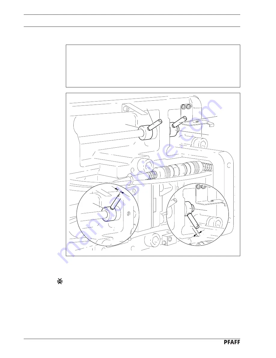
Mechanical limiting of the stitch length

Requirement

1. The maximum stitch length should be 2.5 mm, but the needle should not touch the

needle plate cutout when sewing forwards or in reverse.

2. When the maximum stitch length is set, when sewing forwards the screws of stop 

1

and when sewing in reverse the screws of stop 

3

 should each have a clearance of

0.3 mm 

to the corresponding metal edge.

Fig. 13 - 15

Switch on the machine and set parameter 849 in accordance with 

requirement 1

, see

Chapter 13.11 Parameter settings.

Select the maximum stitch length on the control panel.

Adjust stop 

1

 (screw 

2

) in accordance with 

requirement 2.

Press the key on the machine head and sew 2 stitches (in reverse).

Adjust stop 

3


(screw 

4

) in accordance with 

requirement 2.

Switch off the machine.

1

2

3

4

89-036

0,3 mm

89-035

0,3 mm

1

3

Содержание 2483-980/31

Страница 1: ...Instruction manual 296 12 18 763 002 Betriebsanleitung engl 06 03 2483 980 31 This instruction manual applies to machines from software version 0307 001 and serial number 2216531 onwards ...

Страница 2: ...on of PFAFF instruction manuals whether in whole or in part is not permitted without our prior permission and not without written indication of the source PFAFF Industrie Maschinen AG Postfach 3020 D 67653 Kaiserslautern Königstr 154 D 67655 Kaiserslautern Redaktion Illustration Verlag Technische Dokumentation D 77901 Lahr ...

Страница 3: ...ollowing parameters are determined and recorded on the machine operation card Depending on the material it may be necessary to determine and enter new parameters before production begins The correct setting of all mechanical machine parts must be ensured before beginning with the basic setting see Chapter 13 Adjustment of the instruction manual for the PFAFF 2483 980 31 1 1 Selection and alteratio...

Страница 4: ... workpiece does not move Value 0 If the zero point of the feed regulator cannot be set by selecting one of the permissible values the mechanical setting must be checked or corrected see Chapter 13 05 11 Zero position of the bottom feed dog in the Instruction Manual The permissible values for parameter 834 are 1 0 and 1 2 Short instructions for Adjustment of the PFAFF 2483 980 31 Short instructions...

Страница 5: ...ructions for Adjustment of the PFAFF 2483 980 31 Short instructions for Adjustment of the PFAFF 2483 980 31 78 007 No VAL 846 91 TE 3 No VAL 846 100 TE 1 4 Adjusting the reverse stitch length Calculating the deviation Press and hold key 1 on the machine head and calculate the deviation as in Section 1 3 Correcting the setting Calculate the value for parameter 847 as described in Section 1 3 Select...

Страница 6: ...wing seam program and sew the program seam depth 3 mm Measure the actual seam depth e g 3 4 mm Select the value for parameter 844 accordingly can be altered in 0 2 mm steps see Section 1 1 No VAL 844 106 TE Rx Tx L L 88 Lo TE Rx Tx L L 88 Lo TE 1 1 0 1 6 3 0 2 1 1 1 6 3 0 5 3 1 2 1 6 4 1 3 0 E Step 4 Tables Table 1 3 Values for the adjustment of the feed regulator static All values for stitch leng...

Страница 7: ...02 Transport within the customer s premises 5 1 5 03 Disposal of the packaging 5 1 5 04 Storage 5 1 6 Explanation of the symbols 6 1 7 Controlelements 7 1 7 01 On offswitch 7 1 7 02 Keys on machine head 7 1 7 03 Pedal 7 2 7 04 Lever for lifting the presser foot 7 2 7 05 Knee switch 7 3 7 06 Lever for adjusting the edge guide 7 3 7 07 Controlpanel 7 4 7 07 01 Screen displays 7 4 7 07 02 Function ke...

Страница 8: ...sewing 10 1 10 02 Programmedsewing 10 2 10 03 Error messages 10 3 11 Input 11 1 11 01 Seam program input 11 1 11 02 Example of a seam program input 11 1 11 03 Formsforrecordingprograms 11 14 12 CareandMaintenance 12 1 12 01 Cleaning the machine 12 1 12 02 Topping up the oil tank 12 2 13 Adjustment 13 1 13 01 Notesonadjustment 13 1 13 02 Tools gauges and other accessories 13 1 13 03 Abbreviations 1...

Страница 9: ...nt of the thread catcher 13 21 13 06 03 Knifeposition 13 22 13 06 04 Front point of reversal of the thread catcher 13 23 13 06 05 Manual trimming check 13 24 13 06 06 Needlethreadtensionrelease 13 25 13 06 07 Readjusting the control cam 13 26 13 07 Adjusting the thread wiper 909 04 13 27 13 07 01 Threadwipermovement 13 27 13 07 02 Threadwiperposition 13 28 13 08 Aligningthelighttransmitter 13 29 1...

Страница 10: ...g sewing tools e g needle roller presser needle plate and bobbin when threading the machine when leaving the machine unattended and during maintenance work the machine is to be separated from the power supply by switching off the On Off switch or by removing the plug from the mains Everyday maintenance work is only to be carried out by appropriately trained personnel Repairs and special maintenanc...

Страница 11: ...st be available to the operating personnel at all times The Instruction Manual must be read before operating the machine for the first time The operating and specialist personnel is to be instructed as to the safety equipment of the machine and regarding safe work methods It is the duty of the user to only operate the machine in perfect running order It is the obligation of the user to ensure that...

Страница 12: ...changes in the machine which may limit its safety 1 05 02 Specialist personnel Specialist personnel are persons with a specialist education in the fields of electrics electronics and mechanics They are responsible for the lubrication maintenance repair and adjustment of the machine The specialist personnel is obliged to observe the following points and must always observe the Notes on Safety in th...

Страница 13: ...hibitor 3 Danger of injury if the machine is started accidentally 1 06 Danger A working area of 1 meter is to be kept free both in front of and behind the machine while it is in operation so that it is always easily accessible Never reach into the sewing area while sewing Danger of injury by the needle Never leave objects on the table while adjusting the machine settings Objects can become trapped...

Страница 14: ...try for sewing lockstitch seams Any and all uses of this machine which have not been approved of by the manufacturer are considered to be inappropriate The manufacturer cannot be held liable for any damage caused by the inappropriate use of the machine The appropriate use of the machine includes the observance of all operational adjustment maintenance and repair measures required by the manufactur...

Страница 15: ...Connectiondata Operatingvoltage 230 V 10 50 60 Hz Max power consumption 400 VA Fuseprotection 1 x 16 A inert Noise data Noise emission level at workplace with a sewing speed of 3600 spm LpA 79 dB A Noise measurement in accordance with DIN 45 635 48 A 1 ISO 11204 ISO 3744 ISO 4871 Net weight of sewing head ca 30 kg Gross weight of sewing head ca 38 kg Subject to alterations Depending on the stitch ...

Страница 16: ... various plastics The electrical equipment consists of plastics and copper The machine is to be disposed of in accordance with the locally valid environmental protection regulations If necessary a specialist is to be commissioned Special care is to be taken that parts soiled with lubricants are separately disposed of in accordance with the locally valid pollution control regulations ...

Страница 17: ... of use Make sure that the machines are always transported upright 5 03 Disposal of the packaging The packaging of these machines consists of paper cardboard and VCE fiber The proper disposal of the packaging is the responsibility of the customer 5 04 Storage The machine can be stored for up to 6 months if not in use During this time it should be protected from dust and moisture For longer storage...

Страница 18: ...f this Instruction Manual certain tasks or important pieces of information are accentuated by symbols The symbols used have the following meanings Note information Cleaning care Lubrication greasing Servicing repairing adjustment maintenance only to be carried out by specialist personnel ...

Страница 19: ...carried out Key 1 Reverse sewing Key 2 Raise the needle without threadtrimming Key 3 Carry out a single stitch Fig 7 02 Fig 7 01 7 Control elements 7 01 On offswitch Before switching on the machine raise the take up lever as far as possible The machine can be switched on or off by turning the on off switch 1 1 3 2 1 ...

Страница 20: ...Neutralposition 1 Sewing 2 Raise presser foot 3 Cut thread reset bobbin thread monitor or bobbin rest thread countfunction Fig 7 03 0 1 2 3 7 04 Lever for lifting the presser foot The presser foot is raised by turning lever 1 Fig 7 04 1 ...

Страница 21: ... value for the reduced stitch length is set with parameter 835 see Chapter 13 11Parametersettings Fig 7 05 1 7 06 Lever for adjusting the edge guide Swing down lever 1 to release the clamp on the edge guide Adjust the edge guide to the desired distance from the needle Swing up lever 1 to clamp the edge guide again Fig 7 06 1 ...

Страница 22: ...e displayed with a triangular marking 2 below or next to the respective function key In the sewing mode all relevant sewing data is displayed and these can be changed directly depending on the status of the machine see also Chapter 10 Sewing During the parameter input the selected parameter number with the corresponding value is displayed see Chapter 13 11 Parameter settings During the seam progra...

Страница 23: ...ey is pressed the foot raised after sewing stop function is switched on or off When the function is switched on the presser foot is raised after sewing stops Foot position after trimming If this key is pressed the foot raised after thread trimming function is switched on or off When the function is switched on the presser foot is raised after thread trimming Threadtrimmer If this key is pressed th...

Страница 24: ...n If this key is pressed twice within 5 seconds while the machine is in the sewing mode the machine switches to parameter input If this key is pressed once while the machine is in the parameter input mode the altered values are stored and the sewing mode is selected Scrolling If this key is pressed the machine scrolls among the displays parameters if more than 4 parameters are directly accessible ...

Страница 25: ...s sufficiently sturdy even during sewingoperations 8 01 Mounting The necessary electricity supply must be available at the machine s location Also a stable and horizontal surface as well as adequate lighting are required at the location Depending on the type of table the method of packaging used may require that the table top be lowered for transport The following is a description of how to adjust...

Страница 26: ...nd commissioning the machine 8 2 8 01 02 Mounting the spool holder Mount the spool holder as shown in Fig 8 02 Insert the spool holder into the hole in the table top and fasten it with the nuts enclosed Fig 8 02 ...

Страница 27: ... 8 03 Connect plugs 1 7 as labelled to the control box Screw the earth cable from the sewing head to earth point A Screw the earth cable 8 from the motor to earth point B Connect earth point C and earth point A with an earth cable Fasten the earth cable of the main switch 9 to earth point A 1 2 5 6 3 C 4 A B 8 9 7 ...

Страница 28: ...ions Examine the machine in particular the electric cables for any damage Clean the machine thoroughly see also Chapter 12 Care and Maintenance Have qualified personnel check whether the machine can be operated with the available voltage and whether it is connected properly If there are any irregularities do not operate the machine under any circumstances Fig 8 04 1 2 8 03 Switching the machine on...

Страница 29: ...able top After loosening screws 3 move switch 2 until it is touching plate 1 In this position tighten screws 3 1 2 Switch the machine on at the main switch and tilt it over The error message E009 must appear on the control panel If the message does not appear check the setting of the start inhibitor as described in Chapter 8 01 04 Mounting the start inhibitor Set the sewing head upright and acknow...

Страница 30: ...B B B B A 28 0 2 50 0 2 50 0 2 9 8 0 2 9 8 0 2 1 7 17 4 1 5 0 2 4 1 5 0 2 12 85 40 71 5 0 1 339 6 0 3 28 0 2 8 5 50 1 5 1 5 4 5 4 5 1 5 15 5 18 30 R 1 0 2 x R 1 9 2 x 0 5 R 3 0 R 3 0 R 10 R 10 R 10 R 1 0 R 10 R 1 0 R 10 R 1 0 R 1 9 2 x 0 5 180 5 0 5 120 R 1 9 0 5 R 1 0 2 x R 1 9 0 5 30 45 A Y Y M 2 1 Z M 2 1 ...

Страница 31: ...o be separated from the electricity supply by removing the plug from the mains or switching off the On Off switch 9 01 Inserting the needle Switch off the machine Danger of injury due to unintentionalstartingofthe machine Use only system 134 needles Raise needle bar Loosen screw 1 and insert needle 2 until you feel it stop Tighten screw 1 The selection of the correct needle depends on the model of...

Страница 32: ...le 2 and lever 3 simultaneously The bobbin fills up during sewing If the machine is only run for bobbin winding without sewing a hook base must be fitted in the hook Otherwise a jammed thread may damage the hook The tension of the thread on bobbin 1 can be adjusted with knurled screw 4 The bobbin winder stops automatically when bobbin 1 is full If the thread is wound unevenly Loosen nut 5 Turn thr...

Страница 33: ... and remove bobbin case 2 Inserting the bobbin case Press bobbin case 2 until you feel it snap into the bobbin case base Return the machine to its upright position usingboth hands Danger of injury by crushing between the machine and the tabletop Fig 9 03 2 1 81 097 9 04 Inserting the bobbin in the bobbin case Insert bobbin 1 into the bobbin case 2 as shown in the opposite illustration Fig 9 04 2 1...

Страница 34: ...he bobbin thread tension Pass the thread through the slot under the spring as shown in the opposite illustration Adjust the thread tension by turning screw 1 When the thread is pulled the bobbin must rotate in the direction of the arrow Fig 9 05 90 034 5 c m 1 ...

Страница 35: ...the needle thread Adjusting the needle thread tension Fig 9 06 Switch off the machine Danger of injury due to unintentional starting of the machine Thread the machine as shown in Fig 9 06 Adjust the needle thread tension by turning disk 1 1 ...

Страница 36: ... displayed Adjust the stitch length by pressing the corresponding key 2 0 9 08 Entering the maximum speed Switch on the machine Press the TE Speed key to call up the input menu for the maximum speed The status texts Speed and TE appear on the display Set the maximum speed by pressing the corresponding key No SPEED 220 4500 SPEED TE SPEED ...

Страница 37: ...ing the corresponding key select the desired value for the number of forward stitches A of the start backtack By pressing the corresponding key select the desired value for the number of reverse stitches B of the start backtack By pressing the corresponding key select the desired value for the number of reverse stitches C of the end backtack By pressing the corresponding key select the desired val...

Страница 38: ... B see Chapter13 11 02 Selecting the user level 2 x Select the parameter 760 by pressing the corresponding key By pressing the corresponding key set the number of remaining stitches which can still be sewn after the detection of the bobbin thread monitor depends on the thread size By pressing the TE Speed key the value is taken over and the machine changes to the sewing mode The bobbin thread rest...

Страница 39: ... 7 01 Main switch and the manual sewing mode has been selected with the PM key the display appears for entering the stitch length also see Chapter 9 07 Entering the stitch length If the backtack function is switched on the display appears for entering the backtack values also see Chapter 9 09 Entering the start and end backtacks It is possible to switch from one display to the other by pressing th...

Страница 40: ... seam section and stitch length If other functions such as sensor or stitch count have been activated it is possible to switch to other displays for entering corresponding values by pressing the scroll key The number of backtack stitches is set in manual sewing see Chapter 9 09 Entering the start and end backtacks The values entered apply to all seam programs Functions in programmed sewing also se...

Страница 41: ...hort instructions An error message is caused by incorrect settings faulty elements or seam programs as well as by overload conditions For an explanation of the error codes see Chapter 13 12 Explanation of the error messages Correcttheerror Acknowledge error correction by pressing the TE Speed key ERROR E009 PRESS TE SPEED ...

Страница 42: ...put In this chapter the input of seam programs is described 11 01 Seam program input Switch on the machine Press the PM key to call up programmed sewing The text PM must appear on the display 15 0 2 0 PM 11 02 Example of a seam program input A seam program consists of the program number and at least one seam section with allocated functions Below is an example of a seam program input for a spade p...

Страница 43: ...ar on the display 15 0 2 0 PM Selecting the program number Select program number 7 with the corresponding key 7 0 2 0 PM 1 7 0 2 0 2 7 1 2 0 15 3 7 2 2 0 3 4 7 3 2 0 1 5 5 7 4 2 0 6 0 6 7 5 2 0 1 5 7 7 6 2 0 0 8 8 7 7 2 0 3 9 7 8 2 0 15 10 7 9 0 0 E A B C D Overview of the input steps example Step ...

Страница 44: ... on The presser foot should be raised at the end of the seam section The machine should stop at the end of the seam section The end of the seam section should be recognised by stitch counting 15 stitches The seam section should be sewn at a constant speed Press the start backtack key to switch on the backtacking function at the beginning of the seam To enter the number of stitches for start and en...

Страница 45: ...e should stop at the end of the seam section The end of the seam section should be recognised by stitch counting 3 stitches The seam section should be sewn at a constant speed Press the scroll key to enter the number of stitches With the corresponding key enter the value 15 for the number of stitches Press the scroll key to be able to select the next seam section 7 2 2 0 PM 7 1 2 0 PM 15 PM 7 1 2 ...

Страница 46: ...r of stitches Press the speed key to sew the seam section at a constant speed irrespective of the pedal position Press the scroll key to enter the number of stitches With the corresponding key enter the value 3 for the number of stitches Press the scroll key to be able to select the next seam section 7 2 2 0 PM 3 PM 7 2 2 0 PM Selecting seam section 3 Select seam section 3 with the corresponding k...

Страница 47: ...omatically at the end of the seam section Press the sensor key for recognition of the end of the seam section by sensor 7 3 2 0 PM 7 3 2 0 PM Press the scroll key to enter the seam depth With the corresponding key set the value for the seam depth at 1 5 The actual value for the seam depth is made up of the desired seam depth and the appropriate positive or negative correction value when the angle ...

Страница 48: ... seam section The machine should stop at the end of the seam section The end of the seam section should be recognised by sensor 0 8 mm seam depth Press the programmed stop key to stop the machine automatically at the end of the seam section Press the sensor key for recognition of the end of the seam section by sensor 7 4 2 0 PM 7 3 2 0 PM Press the scroll key to enter the seam depth 6 0 PM ...

Страница 49: ...g the functions for seam section 5 The presser foot should be raised at the end of the seam section The machine should stop at the end of the seam section The end of the seam section should be recognised by sensor 0 8 mm seam depth Press the programmed stop key to stop the machine automatically at the end of the seam section Press the sensor key for recognition of the end of the seam section by se...

Страница 50: ...eam section Selecting the functions for seam section 6 The presser foot should be raised at the end of the seam section The machine should stop at the end of the seam section The end of the seam section should be recognised by sensor 0 8 mm seam depth Press the programmed stop key to stop the machine automatically at the end of the seam section Press the sensor key for recognition of the end of th...

Страница 51: ...for the seam depth is made up of the desired seam depth and the appropriate positive or negative correction value when the angle on the ma terial is not equal to 90 Press the scroll key to be able to select the next seam section 7 6 2 0 PM 0 8 PM Selecting seam section 7 Select seam section 7 with the corresponding key 7 7 2 0 PM 7 6 2 0 PM ...

Страница 52: ...machine automatically at the end of the seam section Press the stitch counting key to enable recognition of the end of the seam section by the number of stitches Press the speed key to sew the seam section at a constant speed irrespective of the pedal position Press the scroll key to enter the number of stitches 7 7 2 0 PM With the corresponding key enter the value 3 for the number of stitches Pre...

Страница 53: ...nction at the end of the seam To enter the number of stitches for start and end backtacks see Chapter 9 09 Entering start and end backtacks Press the foot position after trimming key to raise the presser foot after thread trimming Press the programmed stop key to stop the machine automatically at the end of the seam section Press the thread trimming key to trim the thread automatically at the end ...

Страница 54: ...r the stitch length at 0 0 By setting the stitch length in seam section 9 at zero seam section 8 is recognised as the last seam section of the seam program and the seam pro gram input is concluded Sewing a test seam With the corresponding key select the seam section 0 or 1 Closing the seam program Select seam section 9 with the corresponding key 7 9 0 0 PM Using the pedal functions sew a test seam...

Страница 55: ...Input 11 14 11 03 Forms for recording programs 1 2 3 4 5 6 7 8 9 10 11 12 13 14 15 E Step A B C D 1 2 3 4 5 6 7 8 9 10 11 12 13 14 15 E Step A B C D ...

Страница 56: ...Input 11 15 1 2 3 4 5 6 7 8 9 10 11 12 13 14 15 E Step A B C D 1 2 3 4 5 6 7 8 9 10 11 12 13 14 15 E Step A B C D ...

Страница 57: ...peration If the machine is operated more than this shorter intervals are recommended 12 01 Cleaning the machine Switch off the machine Danger of injury due to unintentionalstartingofthe machine Tilt back the machine Clean the hook and hook compartment daily more often if in continuous operation Return the machine to its upright position usingboth hands Danger of injury by crushing between the edge...

Страница 58: ...e sewing head support Fill oil through hole 1 into the reservoir 2 up to the level of the front edge see arrow Return the machine to its upright position usingboth hands Danger of injury by crushing between the machine and the tabletop Only use oil with a mean viscosity of 10 0 mm2 s at 40 C and a density of 0 847 g cm3 at 15 C We recommend PFAFF sewing machine oil part no 280 1 120 105 Fig 12 02 ...

Страница 59: ...s must be observed Screws nuts indicated in brackets are fastenings for machine parts which must be loosened before adjustment and tightened again afterwards Unless stated otherwise during all adjustment work the machine must be disconnected from the electric and pneumatic power supply Danger of injury if the machine is started accidentally 13 02 Tools gauges and other accessories 1 set of screwdr...

Страница 60: ... position Insert blocking pin 1 in hole Turn balance wheel slightly back and forth until blocking pin engages crank 2 Needle bar position 0 6 mm past t d c Set needle bar roughly at required position Place adjustment gauge 3 onto pins 4 and 5 making sure right side is used for 30 or 36 mm needle bar stroke Needle bar position 0 6 mm past b d c Set needle bar roughly at required position Place adju...

Страница 61: ... positioned 0 6 mm past b d c the markings 3 and 4 should be in alignment Fig 13 02 Bring needle bar to 0 6 mm past b d c Adjust the toothed belt wheel 1 according to the requirement and slide on toothed belt 2 When installing the motor pay attention to the correct position of shaft flange shock absorber and motor flange The second screw on the toothed belt wheel 1 is a cornet screw 57 42a 3 4 1 2...

Страница 62: ...m above BDC the mark on the needle bar 1 must be flush with the bottom edge of the needle bar frame 3 Fig 13 03 Set needle bar at 1 8 mm past b d c and block machine with blocking pin see Chapter 13 04 Checking and adjusting aids Move needle bar 1 screw 2 without turning it according to the requirement 2 1 3 ...

Страница 63: ...l is turned Fig 13 04 Before starting the adjustment disconnect the pedal rods Danger of injury in the machine suddenly starts up Switch on the machine On the control panel set the stitch length at 0 and turn the balance wheel until the stitch length control motor reacts Make sure that parameter 834 is set at 0 see Chapter 13 11 Parameter settings Adjust tooth segment 1 screws 2 according to requi...

Страница 64: ...equirement With the needle bar positioned 0 6 mm past b d c the bottom feed dog should not move when shaft 3 is turned backwards and forwards 3 Position the needle bar at 0 6 mm past b d c Adjust eccentric 1 screws 2 according to the requirement without moving it sideways 1 2 ...

Страница 65: ...The bottom feed dog should be at it the top of its stroke and 2 The control cam 3 should be touching the feed lifting eccentric 1 Set the stitch length at 0 and bring the needle bar into the corresponding position Adjust eccentric 1 screws 2 in accordance with requirement 1 Adjust control cam 3 screws 4 in accordance with requirement 2 Fig 13 06 4 1 3 2 ...

Страница 66: ... the machine and with the control panel set the stitch length at 0 Turn the balance wheel until the feed regulator motor reacts Bring the bottom feed dog 1 to the top of its stroke Raise the presser foot Position the feed dog adjustment gauge 2 over the needle plate cutout with the arrow pointing in the direction of sewing and with its front edge level with the edge of the needle plate Lowerthepre...

Страница 67: ...e needle hole Loosen screws 1 2 and 3 Adjust the needle bar frame 4 in accordance with the requirement Tighten screw 2 and slightly tighten screw 3 Use screw 1 to draw the internal guide pin towards the eye of the needle bar frame 4 and tightenit Turn the balance wheel a few times so that the needle bar frame 4 is not under tension Tighten screw 3 3 2 1 4 Fig 13 08 ...

Страница 68: ...ed belt should be tightened so that when the gauge is placed on it the marking in the gauge window should match the marking on the bushing 1 3 Fig 13 09 Align the hook bearing shaft 1 screw 2 in accordance with requirement 1 Press the gauge part no 61 111 639 76 onto the toothed belt so that it is centred to it and touching the bearing on the rock shaft The gauge window must point towards the hook...

Страница 69: ... seconds a mark should be made by a fine stripe of oil on the strip of paper placed over the needle plate cutout The adjustment is only necessary if the wick has been replaced When replacing the wick make sure that the new wick is impregnated with oil Move the centrifugal disk 1 screw 2 according to requirement 1 Check requirement 2 If necessary move centrifugal disk 1 Fig 13 10 2 1 3 1 5 mm ...

Страница 70: ... of the needle eye must be 0 8 mm below the hook point 3 Between the projection of the bobbin case position finger 4 and the bottom of the retaining groove there should be a distance of 0 5 mm Using the adjustment pin position the needle bar at 1 8 mm after BDC Adjust the hook according to requirement 1 Tighten screw 1 Move needle bar 2 screw 3 without turning it according to requirement 2 Align b...

Страница 71: ...above Move the slack thread regulator 3 screw 4 toward the more thread or toward the less thread Fig 13 12 13 05 11 Thread check spring and slack thread regulator Requirement 1 The motion of the thread check spring must be completed when the needle point enters the material spring stroke approx 7 mm 2 When the thread loop is at its largest when going around the hook the thread check sp ring must h...

Страница 72: ...ised the clearance between the presser foot and the needle plate should be 5 mm Adjust solenoid 1 screw 2 in accordance with requirement 1 Raise the hand lever and place adjustment gauge 3 part no 61 111 639 70 under the presser foot in accordance with requirement 2 Move presser bar lifting lever 4 against lifting piece 5 Make sure that the needle is in the centre of the presser foot Fig 13 13 2 1...

Страница 73: ...in winder Adjust pin 3 screw 4 in accordance with requirement 2 and turn it in accordance with requirement3 13 05 13 Bobbin winder Requirement 1 With the bobbin winder on the drive wheel 1 must engage reliably 2 With the bobbin winder off the friction wheel 5 must not be driven by the drive wheel 1 3 The eccentric pin 3 should be positioned in the centre of the large bobbin chamber 81 043a 3 ...

Страница 74: ...n of the bottom feed dog The zero position of the feed regulator is always recognisable in a range of 3 values When making the adjustment select the middle value Switch off the machine Find more information on how to select and alter parameters and about descriptions functions of the individual parameters in Chapter 13 11 Parameter settings No VAL 834 0 TE Unthreadthemachine Switch on the machine ...

Страница 75: ... of the formula Select the calculated value for parameter 846 and switch off the machine The adjustment of the reverse stitch length is carried out as described in the above work steps under parameter 847 with the reverse feed key pressed see Chapter 7 02 Keys on the machine head More information about selecting and changing parameters and explanations functions of the individual parameters is con...

Страница 76: ...in reverse the screws of stop 3 should each have a clearance of 0 3 mm to the corresponding metal edge Fig 13 15 Switch on the machine and set parameter 849 in accordance with requirement 1 see Chapter13 11Parametersettings Select the maximum stitch length on the control panel Adjust stop 1 screw 2 in accordance with requirement 2 Press the key on the machine head and sew 2 stitches in reverse Adj...

Страница 77: ...13 19 13 05 17 Presser foot pressure Requirement The material must be fed reliably In the process pressure marks on the material must not be made Fig 13 16 89 024 1 Turn screw 1 in accordance with the requirement ...

Страница 78: ...letely extended roller lever 4 should be at the lowest point of the control cam 2 When the needle bar is positioned at 1 8 mm after b d c needle rise position roller lever 4 should engage in the appropriate recess of the control cam Adjust solenoid holder 1 screws 2 in accordance with requirement 1 Adjust control cam 5 screws 6 in accordance with requirement 2 2 3 1 4 89 026 4 6 5 89 025 ...

Страница 79: ...ad catcher 5 must be horizontal It must not graze anything when it is operating Remove knife 1 screw 2 Move needle bar to its BDC Loosen stop 3 screws 4 Position thread catcher 5 screw 6 manually in front of the needle Align thread catcher 5 screws 7 according to the requirements For further adjustments leave knife 1 removed and stop 3 loosened Fig 13 18 6 5 3 1 2 5 6 ...

Страница 80: ... the right edge of the thread catcher see arrow Bring the needle bar to BDC Slide knife 1 under the locking tab and align according to requirement 1 Tighten screw 2 lightly Adjust thread catcher carrier 3 by hand until the wedge point in the thread catcher is positioned just in front of the cutting edge of the knife Align knife 1 according to requirement 2 and tighten screw 2 Fig 13 19 1 1 2 4 mm ...

Страница 81: ... front point of reversal of thread catcher 4 the tip of the thread catcher cutout should be 1 mm in front of the bobbin case position finger 5 Fig 13 20 Position roller lever 1 at the lowest point of the control cam Adjust bush 2 screws 3 according to the requirement 1 2 3 5 4 1 mm 89 025 1 ...

Страница 82: ...its front point of reversal Double the thread and insert into catcher cutout Carry out trimming operation manually If the threads are not cut according to the requirement align thread catcher 1 screws 2 with knife 3 accordingly Move stop 4 against thread catcher 1 and tighten screws 5 Check chapter 13 06 02 Lateral alignment of the thread catcher and readjust if necessary 89 027 2 1 5 4 3 1 ...

Страница 83: ... stroke should be 1 5 mm 2 When the solenoid 5 is operated by hand there should be a distance of at least 0 5 mm between the tension disks 6 Fig 13 22 Adjust disk 1 nuts 2 in accordance with requirement 1 Adjust screw 3 nut 4 in accordance with requirement 2 3 4 5 57 05 0 5 mm 6 2 1 ...

Страница 84: ... 26 Fig 13 23 13 06 07 Readjusting the control cam Requirement When the take up lever is in its t d c control cam 1 should have moved thread catcher 3 Adjust control cam 1 screws 2 according to the requirement 1 2 3 ...

Страница 85: ...d wiper 5 is to move under the needle point and clear it by approx 1 mm when the engaging solenoid 2 is operated Bring the take up lever to TDC Loosen screws 1 Push thread wiper 2 parallel to the bedplate to the very top and tighten screws 1 slightly Turn bracket 3 screw 4 according to requirement 1 Move thread wiper 2 parallel to the bedplate according to requirement 2 Tighten screws 1 Fig 13 24 ...

Страница 86: ...ction of sewing 1 The point of the thread wiper 5 must be approx 1 1 5 mm to the right of the needle 2 The thread wiper 5 must be approx 2 mm in front of the needle in its foremost position Slide bracket 1 screw 2 without turning it on the shaft according to requirement 1 Turn rod 3 nut 4 according to requirement 2 ...

Страница 87: ...rs PS2 and PS1 should display the same value same receiving power Switch on the machine Select the PS function from the service menu see Chapter 13 13 Service functions Adjust light transmitter 1 screw 2 in accordance with the requirement Switch off the machine Fig 13 39 FKT PS2 PS1 Tx PS 34 34 Lo SERVICE 2 1 ...

Страница 88: ...on the corresponding key Move the material plies to and fro under the sensors for a short time To end the adjustment for two material plies press on the corresponding key If necessary increase or reduce the transmitting power with the corresponding key Press the F3 key and sew a test seam Switch off the machine 13 09 Adjustment of the transmitted light sensors Requirement The difference between on...

Страница 89: ... of the bobbin thread monitor Place the bobbin in the bobbin case and the bobbin case in the hook Switch on the machine Select the TM function from the service menu see Chapter 13 13 Service functions Pull the thread by hand and check the requirement If necessary increase or reduce the transmitting power with the corresponding key Switch off the machine Fig 13 40 Tx FKT Rx Tx TM 1 12 SERVICE ...

Страница 90: ...ocked to avoid the machine starting accidentally Select the desired parameter e g 660 bobbin thread control by pressing the corresponding plus minus key With the corresponding plus minus key set the desired value for the parameter e g 0 to switch off the bobbin thread control function No No VAL 660 1 TE VAL 2 x By pressing the TE Speed key the value is taken over and the machine switches to the se...

Страница 91: ...No VAL 798 0 TE Press the TE Speed key to take over the value and change to the sewing mode When the main switch is switched off the machine changes automatically to user level A VAL No VAL 101 on TE By pressing the corresponding key select the desired user level 0 Operator level A 1 Mechanic level B 11 Service level C The respective level is displayed on the screen see arrow No VAL 798 1 TE A B 2...

Страница 92: ...hold 18 Light sensors upper hysteresis value C 10 90 35 for threshold 20 Light sensors C 0 255 0 Min value for 2 plies 21 Light sensors C 0 255 0 Max value for 2 plies 22 Light sensors C 0 255 66 Threshold from 2 1 ply 23 Lightsensorscurrentthreshold C 0 255 70 24 Light sensors C 0 255 74 Threshold from 1 2 ply 25 Light sensors C 0 255 200 Min value for 1 ply 26 Light sensors C 0 255 255 Max value...

Страница 93: ...backtacks speed C OFF ON OFF ON pedal controlled OFF set with param 105 107 Pedal controlled speed start backtacks C OFF ON OFF ON limited with parameter 105 OFF limited with parameter 607 108 End backtacks in reverse C 0 9 3 109 End backtacks forwards C 0 9 3 110 End backtacks speed B 100 1500 1000 111 No of stitches from bright light barrier A 1 255 6 to seam end in manual sewing 113 Start with ...

Страница 94: ... min 1 298 Number of reduced stitches A 0 3 1 299 Edgeguideposition A 10 185 185 in manual sewing 1 10 mm 4 419 Bartacks C OFF ON ON ON inverted OFF suppressed 492 Number of seam programs B 1 99 15 493 Number of seam segments per seam program B 1 15 15 5 554 Presser foot after seam segment C OFF ON ON with pedal forwards ON raised OFF lowered 584 Backtack stitches C OFF ON OFF ON fourfold OFF norm...

Страница 95: ...ON ON 642 Presser foot time from switch on C 10 50 50 to tension reduction tacting 643 Feed conversion time from C 10 200 100 switch on to tension reduction tacting 651 Automatic lowering of presser foot C OFF ON ON ON ein OFF aus 660 Bobbinthreadmonitoring A 0 2 1 0 off 1 on 2 bobbin thread reverse counter on 665 Startinhibitor C OFF ON OFF ON when contact closed OFF when contact open 668 Thread ...

Страница 96: ... 50 steep 723 Brake ramp C 4 50 50 1 flat 50 steep 729 Start delay after B 0 2550 120 lowering presser foot ms 730 Lift delay B 0 2550 0 for presser foot after seam end ms 731 Stitch count delay for end backtack C 0 2550 70 732 Delay time for cutting C 0 2550 30 after single end backtack ms 733 Delay time from C 0 200 30 switch on feed conversion to speed start ms 739 Delay time for speed C 0 2550...

Страница 97: ...ing direction of stepping motor 1 C OFF ON ON 831 Start delay for B 0 10 5 stepping motor 2 increments 832 Needle position feed start B 0 127 77 833 Needle position feed end B 0 127 0 834 Feedregulator balance B 5 5 0 1 semi step 5 100mm 835 Reduced single stitch A 0 100 50 843 Distance sensor 1 to sensor 2 B 75 85 80 1 10mm 844 Distance sensor 1 to needle 2 10mm B 80 300 200 845 Speed controlled ...

Страница 98: ...ion C 0 50 35 of the speed control 886 Proportionalamplification C 1 50 30 of the position controller 887 Differentialamplification C 1 50 30 of the position controller 889 Time for position control 0 permanently C 0 2550 200 890 Proportionalamplificationof C 1 50 25 higherrankingspeedcontroller for standstill brake rest brake 891 Proportionalamplificationof C 1 50 20 subordinatespeedcontroller fo...

Страница 99: ...int low in operation E066 Shortcircuit E067 Poweroff E068 Extint low in operation E069 Noincrements E070 Motorblocking E071 Noincrementalconnector E072 No set value connector E073 Motorrunninginterrupted E075 Controllerlocked E092 Startinhibitorwhenmotorrunning E151 System E155 Sewingmotor E156 Time out communication E157 Steppingmotorramps E158 Steppingmotorfrequency E170 Incorrect main drive tra...

Страница 100: ...OFF SERVICE The individual service functions are shown under FKT and can be selected with the corresponding key Overview of the service functions FKT IN Read out inputs With the corresponding key the number of the input No can be selected OUT Set resetoutputs With the corresponding key the number of the output No can be selected and set accordingly VAL ON OFF PED Read out set value transmitter ped...

Страница 101: ...keys the value for the speed is changed accordingly By selecting the type SC and entering the desired value with the corresponding keys the value for the stitch count is changed accordingly RES Carry out reset By selecting the type PAR and confirming the selection with the corresponding keys the values for all parameters are reset master reset By selecting the type PRG and confirming the selection...

Страница 102: ...nction Plugmarking Signalmarking X15 1 Sensors current source UFW P7 3 X15 2 Sensors DLS outside LS2 P5 3 analog X15 3 Sensors DLS inside LS1 P5 6 analog X15 4 Sensors ZZ Sensor 2438 E9 E9 Port_E9 X15 5 Sensors current source DLS A10 PortA10 O10 X15 6 Sensors 5V 5V X15 7 Sensors UFW Out UFW_MESS X15 8 Sensors 24V 24V X15 9 Sensors 0V 0V RS232 Pin No Comment Function Plugmarking Signalmarking X1A 1...

Страница 103: ...t ADTC X3 5 incr transm 5V X3 6 incr transm 5V X3 7 incr transm Gnd X3 8 incr transm Ext SyMa 180 EXTSM_MINI X3 9 incr transm Gnd Stepping motor 1 edge guide Pin No Comment Function Plugmarking Signalmarking X4B 1 SM1 FSL phase A 2 A11 X4B 2 SM1 FSL phase A 1 A12 X4B 3 SM1 phase B 2 A21 X4B 4 SM1 phase B 1 A22 X4B 5 SM1 X4B 6 SM1 X4B 7 SM1 5V with 120R X4B 8 SM1 reference SM1 SM_REF1 SM_REF1 X4B 9...

Страница 104: ...19 SN solenoid Y2 24V 24V X13 20 WI solenoid Y3 24V 24V X13 21 24V 24V X13 22 RAFI LED H1 24V 24V X13 23 24V 24V X13 24 A13 O13 X13 25 A12 O12 Inputs Pin No Comment Function Plugmarking Signalmarking X5 01 TUM key S1 E1 E7 X5 02 NPW key S2 E2 E8 X5 03 EST key S2 E3 E2 X5 04 ANLSP switch S14 E4 E4 X5 05 EST knee switch S13 E5 E5 X5 06 knee switch2 E15 E15 X5 07 E16 E16 X5 08 E14 E14 X5 09 from DX Z...

Страница 105: ...machine Switch off the machine Connect the PC serial interface or appropriateUSB adapter andthe machine control unit RS232 To do so disconnect the plug of the control panel Switch on the PC and start the PFP boot program Select the machine type Press the programming button Hold down boot key 1 and switch on the machine Press the OK button Fig 13 47 1 The software update is carried out the update p...

Страница 106: ...list for the complete machine under parts number296 12 18760 91 262 250 91 99 262 376 91 99 137 187 15 2x 99 137 186 05 99 137 189 05 4x 99 137 188 15 99 137 190 05 3x 91 262 377 91 99 137 192 05 99 137 194 05 99 137 193 05 99 137 191 05 95 774 361 05 91 701 179 15 2x 91 100 296 25 2x 11 108 174 25 11 330 085 15 System 134 ...

Страница 107: ...Wearing parts 14 2 99 137 151 45 91 171 049 05 91 171 042 05 11 108 087 15 91 262 235 15 91 171 853 15 91 108 222 15 91 264 240 15 11 108 084 15 2x ...

Страница 108: ...itch included in A4 S11 Backtacking by hand backtack included in A4 S12 Needle position included in A4 S13 Knee switch single stitch S14 Startinhibitor S15 2nd knee switch H1 Sewing lamp H10 Bobbin thread alarm included in A4 Q1 Main switch M1 Sewingmotor M10 Steppingmotor feedregulator M11 Steppingmotor edgeguide B10 Hybrid light barrier included in M10 Y2 900 thread trimmer Y3 W1 thread wiper Y4...

Страница 109: ...15 2 2483 980 Version27 01 03 Overview ...

Страница 110: ...15 3 Circuit diagram Version 29 01 02 91 191 454 95 Part 1 ...

Страница 111: ...15 4 91 191 454 95 Part 2 Version 29 01 02 Circuit diagram ...

Страница 112: ...15 5 Circuit diagram Version 29 01 02 91 191 454 95 Part 3 ...

Страница 113: ...15 6 91 191 454 95 Part 4 Version 29 01 02 Circuit diagram ...

Страница 114: ...en AG Postfach 3020 D 67653 Kaiserslautern Königstr 154 D 67655 Kaiserslautern Telefon 0631 200 0 Telefax 0631 17202 E Mail info pfaff industrial com Gedruckt in der BRD Printed in Germany Imprimé en R F A Impreso en la R F A ...

Отзывы: