background image

Rev.: 2004-001-GB


12

6.2  Welding with the FUSAMATIC

©

-Mode 

Pay  attention  to  the  installation  instructions  of  the  fitting,  special  instructions  (ISO, 
DVGW, DVS), European and national directions as well as the laying instructions! 


Note: The Monomatic control unit can be used for FUSAMATIC fittings only.  


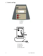
As long as no fitting is connected, no welding  process can be started. Connect  the welding terminals of 
the control unit to the pins of the fitting. Take care on a firm and proper fit. You have to pay attention for 
the  right  connection  between  the  welding  connectors  and  the  fitting  plugs. 

The  red  terminal  must  be 

put  on  the  fitting  pin  which  is  marked  with  the  red  ring.

  Thus  the  welding  device  can  detect  the 

fitting  type  and its welding  parameters.  It  will  switch  to  the  FUSAMATIC

©

-Mode  automatically.  This will 

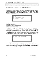
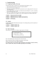
be indicated by the following message: 

START 
Nom. time:  0200s 
FUSAMATIC   40V 
 

Line 1  prompts you to confirm the shown welding parameters. 

Line 2  Shows the welding time. 

Line 3  shows the fitting type and welding voltage. 

Line 4  shows error messages respectively. 

You  have  to  compare the  shown  parameters  with  the  parameters  stated on  the  fitting.  In  the  case  that 
these  deviate  or  if  a 

Contact  error

  is  indicated  in  the  lowest  row  of  the  display,  a  faulty  or  invalid 

reference  resistance  is  read.  Disconnect  the  welding  terminals  from  the  fitting  plugs.  Check  the 
connectors of the fitting and welding cable for dirt or coating. If the fitting causes another 

Contact error


or differing parameters, it is defect. Replace it. 

If no 

Contact  Error

 occurs,  you can confirm the correctness of the welding parameters by pressing the 

green 

START

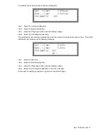
-key.  The  following  message  will  remind  you  of  your  duty  to  fix  and  prepare  the  pipes 

according to the general guidelines: 

Is the pipe scraped ? 


If you have any doubt about the right  preparation, you can break off the procedure by actuating the red 

STOP

-key. Otherwise confirm the proper preparation by pressing the green 

START

-key.  

The welding device starts the welding process automatically. 

To avoid danger for your health, do not 

touch the fitting or cables during the welding process.  

Содержание monomatic

Страница 1: ...e G m b H Ka rl Br ge r St r 10 DE 36304 A lsfe ld T el 49 6631 9652 0 Fa x 49 6631 9652 52 System Welding Device PF monomatic PF Schwei technologie GmbH Karl Br ger Str 10 DE 36304 Alsfeld Tel 49 0 6...

Страница 2: ...Rev 2004 001 GB 2 Rev 2004 001 GB...

Страница 3: ...ontrols and Plugs 8 5 Power Connection 9 5 1 Generator suitability 10 6 Starting a welding process 10 6 1 Preparation 10 6 2 Welding with the FUSAMATIC Mode 12 7 Other Functions 14 7 1 Function menu 1...

Страница 4: ...should be carried out more often During the maintenance the machine will be upgraded to the current technical state Additionally you get a 3 month function guarantee for the maintained device The main...

Страница 5: ...er to an ambient temperature of 20 C 2 4 Technical data Technical Data Technische Daten Monomatic ISO 12176 2 Class Klassifizierung P2 3 U S1 F A M Input Voltage Eingangsspannung 230V AC 185V 300V Inp...

Страница 6: ...Rev 2004 001 GB 6...

Страница 7: ...ldren away Do not allow other people touch the device or cables keep them away from your working place 5 Store up your device safely Unused machines should be kept in a dry and locked room inaccessibl...

Страница 8: ...Rev 2004 001 GB 8 4 Controls and Plugs 1 DISPLAY 2 START 3 STOP 7 6 5 4 4 Power Switch 5 Welding Cable 6 Cable Holder 7 Power Supply Cable...

Страница 9: ...s shall not be used at 230V power supply and vice versa When operating on a electric distributor or the main power supply of nominal 230V a min 16 Amps slow fuse comprising a residual current operated...

Страница 10: ...20 75 mm 2kW 90 160 mm 3 2kW 180 710mm 4 5kW mechanically controlled 5kW electronically controlled For generators with insufficient control performance or voltage control it has to be selected 3 3 5...

Страница 11: ...input voltage In case of generator use check that the voltage is at about 240 260V at nominal 230V nominal 110V 120V 130V AC Line 3 shows the input frequency Line 4 indicates that no fitting in conne...

Страница 12: ...elding time Line 3 shows the fitting type and welding voltage Line 4 shows error messages respectively You have to compare the shown parameters with the parameters stated on the fitting In the case th...

Страница 13: ...r messages respectively The welding process will stop automatically when the actual time reaches the nominal time This will be indicated by two bleeps and the following message Act time 0200s Nom time...

Страница 14: ...u item START short Moves the cursor upwards STOP short Moves the cursor downwards START 3 sec Selects the marked menu item STOP 3 sec Cancels the function menu 7 2 Adjusting the display contrast By se...

Страница 15: ...the system configuration menu the display will show a list of language indicators GB SE ES The indicators stand for GB English SE Swedish ES Spanish IT Italian DK Danish PT Portuguese DE German FR Fr...

Страница 16: ...Welding Terminal 4 7mm standard 1_0200_003 Welding Terminal 4 0mm standard 2_0200_003 Welding Terminal 4 7mm Fusamatic with detection tip 2_0200_004 Welding Terminal 4 0mm Fusamatic with detection ti...

Страница 17: ...ature of transformer is too high Let the device cool down for about 45 min Emergency cut out Welding was interrupted by pressing the STOP key Welding is faulty Frequency error Input frequency out of w...

Страница 18: ...tacts Use an other fitting Service The recommended service interval of 12 months or 200 working hours is exceeded The device has to be checked by an authorized service point The device is still usable...

Страница 19: ...Rev 2004 001 GB 19 9 Conformity Declaration...

Страница 20: ...Rev 2004 001 GB 20...

Страница 21: ...Rev 2004 001 GB 21...

Отзывы: