8
VB 230/400-25
8.
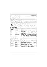
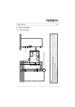
Control inputs and outputs
8.1
Control inputs
Caution: Danger to life through electric shock!
The terminals X3 and X4 carry mains potential. If a switch or contactor
contact is connected to these terminals, it must have a test voltage of 2.5kV.
8.2
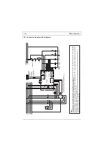
Control outputs
8.3
Control outouts – optional
Control
terminals
Designation
Description
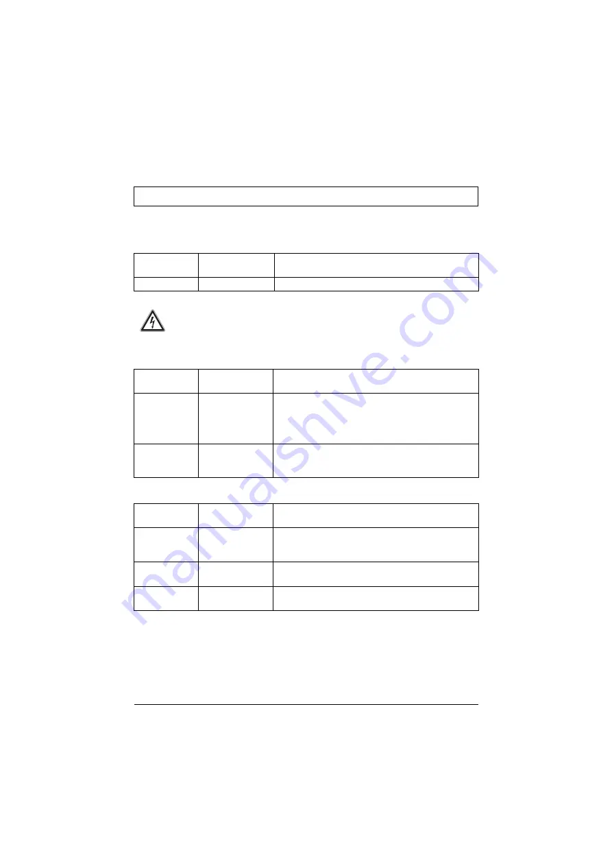
X3, X4
Starting contact
Connection of a break contact of the motor contactor
Control
terminals
Designation
Description
X5, X6
Interlock
The interlock prevents the motor from being switched on
during braking.
Loop the normally closed contact into the branch of the
motor contactor.
X7, X8
Fault signal
In the case of a fault this fault signaling contact opens.
For closer details on the tripping characteristics please
see chapter 5.2, page 6.
Control
terminals
Designation
Description
X16, X17
Standstill indica-
tion in the case of
option „S“
In the case of standstill-dependent braking, a contact
can be evaluated. For closer details regarding the trip-
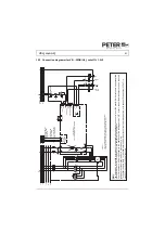
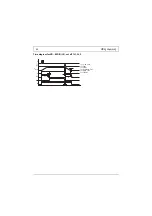
ping behavior please refer to chapter 8.4 on page 9.
X12, X11
Υ - contactor with
option „D“
Control contact for the star contactor. For closer details
please refer to chapter 8.3 on page 9.
X12, X13
Δ - contactor with
option „D“
Control contact for the delta contactor. For closer
details please refer to chapter 8.3 on page 9.

