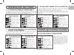

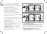
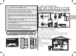
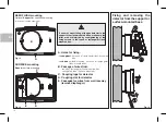


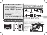
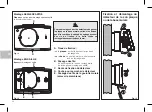


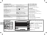

Fig. 16a:
Example: connection to normally
closed solenoid valve
Fig. 16b:
Example: connection to normally
open solenoid valve (manual re-arm)
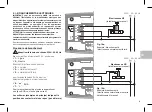
230V~ 50÷60 Hz
NO solenoid valve
(manual re-arm)
230V~ 50÷60 Hz
19
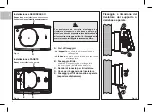
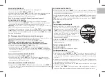
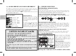
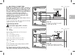
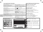
switch mains supply off 230V~ 50-60 Hz
Connect 230V ~ power supply to the terminals:
n° =
1
Line
n° =
2
Neutral
Connect the controlled device to the terminals:
n° = common
3
n° = normally open contact
4
n° = normally closed contact
5
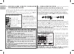
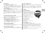
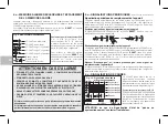
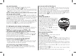
2.i - ELECTRICAL CONNECTIONS
Connection procedure
The diagrams (
examples) show
purely guideline
the position of the relay contacts at rest (no alarm)
WARNING: the main appliance's must include a device
ensuring omnipolar disconnection.
For the connection of several appliances to a BUS
line, see the next chapter.
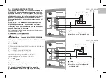
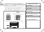
n° = “
”
6
n° = “ ”
7
+
BUS
For the electrical connections, attach the detector terminals using
cables of cross-section 1.5 mm maximum.
2
IMPORTANT: the installation and electrical connection of
devices and appliances must be carried out by qualified
personnel and in compliance with standards and laws in
force. The appliance is suitable only for applications in
household or similar environments. For application in special
environments, see specific environment standards.
The examples given in this documentation are indicative.
The detector must be powered continuously in order to
guarantee maximum safety.
In the case of BUS connection to other
detectors/indicators, use the terminals:
EN
NC solenoid valve
(manual re-arm)
Содержание 1GA47917GPL/P
Страница 53: ...53 NOTE NOTES ANMERKUNGEN NOTAS...