Brake release sensor & Actuator control board
22
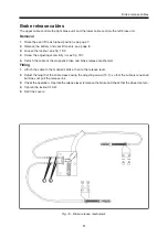
Fig. 48. Detachment of Actuator control board
Brake release sensor
Removal
1.
Detach the seat lift and chassis covers,
see page 8.
2.
Switch off the power using the control panel.
3.
Set the main fuse to the “OFF” position,
see page 20.
4.
Detach the brake release sensor’s base by
loosening the two screws, see fig. 47.
5.
Separate the connector in the connection cable.
Installation
Installation is the reverse procedure.
Seat electronics
Actuator Control Board
Removal
1.
Detach the seat lift and chassis covers,
see page 8.
2.
Switch off the power using the control panel.
3.
Set the main fuse to the “OFF” position,
see page 20.
4.
Detach the case and the actuator control
board by unscrewing and removing the two
screws, see fig. 48.
5.
Loosen all cable connections sitting on the
card. Take careful note of the placement of the
cables with an eye towards their future
remounting.
Installation
Installation is performed in the reverse order.
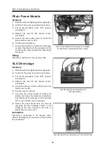
Fig. 49. Detached Actuator control board.
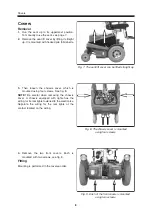
Fig. 47. Brake release sensor
Содержание Chairman Playman
Страница 1: ...SERVICE MANUAL US Chairman Playman Robo ...
Страница 2: ......
Страница 24: ...Distribution Chart 24 A B C D E F 1 2 3 4 ...
Страница 25: ...Distribution Chart 25 Distribution Chart A B C D E F 5 6 7 8 ...
Страница 26: ...Notes 26 ...
Страница 27: ......
Страница 28: ...Order no 201162 US 0 ...


