Sprayer Operation
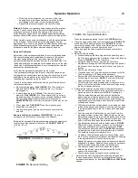
Method 2
: Make trim-pass and header-pass as in the previous
section. Fill in the center making squared-off descending spiral
passes to the center spraying as needed.
Either method may be used simultaneously with the spreader
features on the machine on the center of the lawn. (
NOTE
: For best
spray results, you may make separate granular and liquid trim-
passes, and/or use a spot sprayer to lightly feather the edge of the
spray along the borders adjacent to drives, sidewalks etc.) Refer to
Spreader Operation for detailed instructions.
Adjusting Nozzles for proper spray pattern
IMPORTANT: Check and adjust the Spray pattern of ALL
Nozzles daily, prior to treating each lawn, and as needed to verify
that the nozzles are properly aligned and spraying properly.
Adjusting the Broadcast Spray pattern
Park on a flat, concrete or asphalt surface.
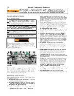
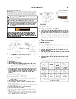
Referring to
FIGURE 15
, select the
HIGH GEAR
Broadcast
Nozzle (
TF-VS 7.5-90
color coded with a green band) by
turning the front Spray Control Valve (
I
) handle to the left. The
rear Spray Selector Valve handle (
J
) must be pointed forward
turning off the
LOW GEAR
nozzles. [If the Half Gallon Nozzle Kit
is installed, both Broadcast Nozzles will be used
simultaneously.]
With the machine in
NEUTRAL
and running, pull the throttle
lever to full operating speed of
3450 RPM
, and pull the Spray
Lever.
Spray for
15 SECONDS
until the spray pattern is visible on the
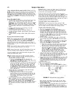
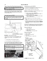
surface. The spray pattern should resemble the
11-14 FEET
spray pattern in
FIGURE 17
. Adjust as follows:
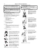
Rotate the nozzle body on the pipe nipple so that the spray
pattern comes out slightly below parallel with the ground.
Adjust the spray nozzle body so that the pattern width,
measured from outermost droplets to outermost droplets
should be
11 FEET
(3.4 meters) using the
20 PSI
Unloader
Valve or
14 FEET
using the
30 PSI
Unloader Valve.
Increase the pattern width by raising the nozzle level.
Decrease the pattern width by lowering the nozzle level.
Install a bolt from the user-installed Nozzle locating Kit
(enclosed in the parts bag in the Hopper) against the front edge
of the nozzle Cap. If the nozzle body has been moved return it
to the calibrated setting by touching it to the bolt.
Repeat the procedure for the
LOW GEAR
Broadcast Nozzle (
TF
-
VS4-90
color coded with a white band). Remember to turn
off the
HIGH GEAR
Spray Selector Valve. [If the Half Gallon
Nozzle Kit is installed, both Broadcast Nozzles will be used
simultaneously.]
Adjust the trim spray pattern
Park on a flat concrete or asphalt surface.
Referring to
FIGURE 15
, select the
HIGH GEAR
Trim Nozzle
(
DG Tee Jet 9504 EVS
color coded red) by turning the front
Spray Selector Valve handle (
I
) to the right. The rear Spray
Selector Valve handle (
J
) must be pointed forward turning off
the
LOW GEAR
nozzles.
With the machine in neutral and running, pull the throttle lever to
full operating speed of
3450 RPM
, and pull the Spray Lever.
Spray for
15 SECONDS
until the spray pattern is visible on the
surface. The spray pattern should resemble the
3-FOOT
spray
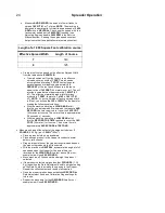
If your calibrated effective spreader width is 8 feet,
install the
30 PSI
unloader cap from the Unloader Valve included in the
8
FOOT
Spray Kit supplied with the machine and adjust the
effective spray pattern to
8 FEET
solid spray and an overall width
of
14 FEET
. trim nozzle provides an even finished distribution over
a spray pattern of
4-FEET
(1.22 meters) on the surface being
treated.
Sprayer Operating Controls
To select which nozzle will spray, point the Spray Control Valve
handle for the gear selected to the desired nozzle either
Broadcast or Trim. The front Spray Selector Valve (
I
) is used for
HIGH GEAR
and the rear Spray selector Valve (
J
) for
LOW
GEAR
. Point Valve Handle left for Broadcast spraying, right
for Trim spraying, and forward to prevent spraying for either
nozzle.
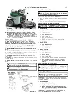
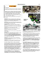
To begin momentary spraying, pull the Spray Lever (
H
)
(
FIGURE 16
) toward the handgrip.
To stop momentary Spraying, release the Spray Lever.
To begin continuous spraying, pull the Spray Lever toward the
handgrip and lock.
To stop continuous spraying, pull and release the Spray Lever
again.
Applying Products with the Sprayer
NOTE: For proper spraying the engine RPM (measured with
the machine in NEUTRAL) MUST be maintained at 3450 RPM,
regardless of whether you are using HIGH or LOW GEAR. If
engine RPM is too low the spray applied will be more than your
Calibrated Rate. If too high, the spray applied will be less than your
Calibrated Rate..
NOTE: For proper spraying, the sprayer calibration must be
verified (refer to Sprayer Calibration in this section).
NOTE: Unless the optional One Half Gallon Spray Kit is used,
Triumph is intended to spray using only one Nozzle at a time.
It is recommended that the products be applied using one of the
following methods for best results.
Method 1
: Make edging pass followed by parallel passes.
Make trim pass around the perimeter of the property and any
ornamental beds spraying as needed.
Select the appropriate gear for the terrain and turf
conditions. Use
LOW GEAR
on hills and in tight areas. Use
HIGH GEAR
on level and open areas.
Select the appropriate Trim Nozzle for the gear selected and
confirm that the other Spray Control Valve is off. Make the
edging pass keeping the edge of the spray pattern inside
the edge of the sidewalk or ornamental bed, spraying as
needed
NOTE
: For best results use a spot sprayer to lightly
feather the edge of the spray along the borders adjacent to
drives, sidewalks etc.
When edging pass is completed stop, make a header pass
overlapping into the first trim pass.
Change gears if desired; and select the appropriate
Broadcast Nozzle for the gear selected and check that the
other Spray Control Valve is off. [If the Half Gallon Nozzle
Kit is installed, both Broadcast Nozzles will be used
simultaneously.]
Fill in the center of the lawn by making parallel passes on
7-
FOOT
or
8-FOOT
centers (corresponding to the Unloader
Valve installed) spraying as needed. At the end of each pass,
enter into the header pass and make a
180 DEGREE
turn.
NOTE
: Avoid re-spraying the areas within the header pass and
trim-pass that were previously sprayed by the effective width
patterns.
26
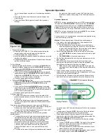
FIGURE 17
, Broadcast spray pattern
11 to 13 feet
Содержание E1E
Страница 4: ...Page left intentionally blank iii...
Страница 8: ...Page left intentionally blank 4...
Страница 24: ...Page left intentionally blank 20...
Страница 36: ...Page left intentionally blank 32...

