


- -
perma PRO
Table of Contents
The lubrication system perma PRO
1
Quick reference guide
2
Content
1.
Various
4
1.1
Delivery / Content
1.2
Storage
1.3
Markings
1.4
Intended Usage
1.5
Legal Requirements
2.
Safety Instructions
6
2.1
Persons Responsible for Safety
2.2
General Safety Instructions
2.3
Safety Information for perma PRO
.
Technical Data
7
3.1
Design of the perma PRO Lubricator
4.
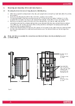
Mounting and Assembly of the Lubrication System
9
4.1
Mounting the Drive Unit onto a Fixing Device for Wall-Mounting
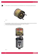
4.2
Assembly of the Lubricator
5.
Display and Control Elements of the Lubrication System
12
5.1
Display Elements
5.2
Function Indication on the Display
5.3
Function Indication via the LEDs
5.4
Control Buttons
6.
Operation and Control
1
6.1
Preparations
6.2
Prior to Operation
6.3
Setting into Operation
6.4
During Operation
6.5
Switching the Lubrication System On
6.6
Switching the Lubrication System Off
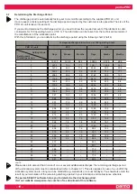
6.7
Determining the Discharge Period
6.8
Settings and Display
6.9
Calculation of the Remaining Discharge Period
7.
Replacement of the PRO LC-Unit
19
7.1
Setting the Volume of the PRO LC-Unit
7.2
How to Replace the PRO LC-Unit
8.
Trouble Shooting
21
8.1
Error Messages on the Display
8.2
Trouble Shooting Guide
9.
Accessories and Spare Parts
22
10.
Disposal
24
11.
Service
24
12.
Conformity Declaration for perma PRO
25