


- 12 -
perma-tec GmbH & Co. KG
The World of Automatic Lubrication
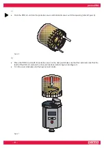
5.
Display and Control Elements of the Lubrication System
5.1
Display Elements
The operating status of the lubricator can be determined via the green or the red LED and via the display at the
control unit (refer to figure 8) of the perma PRO.
The perma PRO offers a menu-guided setting. Changes of the settings are shown on the display. Error
messages, e.g. in case the pressure in the lubricant tube gets too high, are also indicated on the display.
5.2
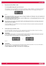
Function Indication on the Display
The display is located on the control unit of the perma PRO (refer to figure 8, chapter 5.1).
The display shows settings, operating conditions and error messages of the lubricator.
In case of an error free operation of the lubrication system, the display shows the remaining volume of the
mounted PRO LC-unit in percent volume (% Vol.). Figure 9 shows an example of the displayed information
if the PRO LC 500-unit is new and full.
The display cannot be switched off by the operator. If the lubrication system is switched off, the display
will always show two lines (see figure 10 below).
figure 9
99
%Vol.
LC
2
500
figure 10
––
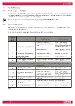
5.3
Function Indication via the LEDs
LED
Signal
Signal Length
Explanation
green
flash
every 10 seconds
operation (OK)
red
flash
every 3 seconds
error / malfunction
green and red
flash
every 3 seconds
PRO LC-unit empty
green
light
permanently
Lubricator is discharging
green and red
none
none
Lubricator switched off or battery low
chart 2
push-button
MODE
SAVE
LCD
Red LED
push-button
ON/OFF
SELECT
Green LED
Connector for
distributor MP-6
figure 8


