SEBU8337
71
Maintenance Section
Engine Valve Lash - Inspect/Adjust
i02568163
Engine Valve Lash -
Inspect/Adjust
The initial valve lash adjustment on new engines,
rebuilt engines, or remanufactured engines is
recommended at the
fi
rst scheduled oil change. The
adjustment is necessary due to the initial wear of
the valve train components and to the seating of the
valve train components.
This maintenance is recommended by Perkins as
part of a lubrication and preventive maintenance
schedule in order to help provide maximum engine
life.
NOTICE
Only quali
fi
ed service personel should perform this
maintenance. Refer to the Service Manual or your au-
thorized Perkins dealer or your Perkins distributor for
the complete valve lash adjustment procedure.
Operation of Perkins engines with incorrect valve lash
can reduce engine ef
fi
ciency, and also reduce engine
component life.
Ensure that the engine can not be started while
this maintenance is being performed. To help pre-
vent possible injury, do not use the starting motor
to turn the
fl
ywheel.
Hot engine components can cause burns. Allow
additional time for the engine to cool before mea-
suring/adjusting valve lash clearance.
Ensure that the engine is stopped before measuring
the valve lash. To obtain an accurate measurement,
allow the valves to cool before this maintenance is
performed.
The following components should be inspected and
adjusted when the valves are inspected and adjusted.
•
Valve actuators
•
Injectors
Refer to Systems Operation, Testing and Adjusting,
“Engine Valve Lash - Inspect/Adjust” for more
information.
i02793537
Fan Drive Bearing - Lubricate
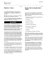
g01395016
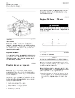
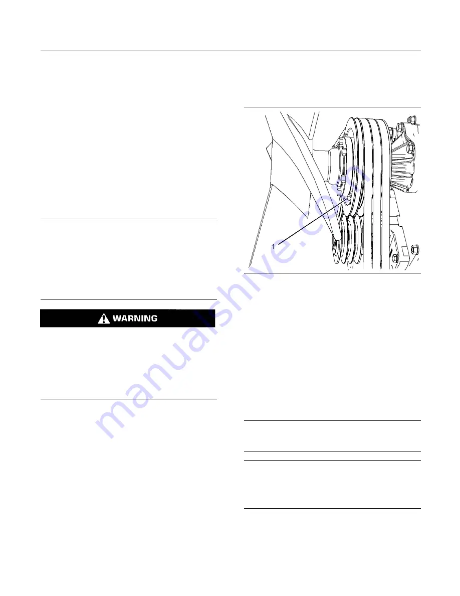
Illustration 39
Typical example
Inspect the fan drive pulley assembly for wear or for
damage. If the shaft is loose, an inspection of the
internal components should be performed. Refer to
the Service Manual for additional information.
Lubricate the grease
fi
tting (1) that is on the fan drive
bearing with
CV3080
Grease.
i02790862
Fuel System - Prime
NOTICE
Use a suitable container to catch any fuel that might
spill. Clean up any spilled fuel immediately.
NOTICE
Do not allow dirt to enter the fuel system. Thoroughly
clean the area around a fuel system component that
will be disconnected. Fit a suitable cover over discon-
nected fuel system component.
1.
Turn the ignition switch to the “OFF” position.
2.
Ensure that the fuel tank is full with clean diesel
fuel. Place a suitable container under the fuel
fi
lters in order to catch any split fuel.

