background image

6

ELECTRICAL

Electrical

1.     Inspect the motors internal wiring to ensure voltage supply is matched between the motor and the 

         power source. If voltage does not match, it will damage the motor and void the warranty. 


Example: If connecting your pump to a 115V circuit, make sure the motor connections match 

                                  the 115V wiring diagram listed on your particular motor. 
2.     Supply voltage must be /- 10% of nameplate voltage indicated on the motor. Incorrect 

         voltage supply may result in fire or damaged motor and voids the warranty. If you are not certain, 

         please consult with a licensed electrician.
3.     Use designated supply wire size specified in the chart below. Correct wire size is necessary to 

         avoid electrical insufficiencies, allowing the motor to run cooler, more efficiently and eliminating line 

         voltage loss. It is important to connect your pump to a ground fault circuit interrupter (GFCI) for safety.
4.     Wire motor following the connection diagram located on the motor. Note differences in high and low 

         voltage arrangements. If a cord has been preinstalled the connection was completed at the factory.
5.     Be sure all connections are clean and tight. Ensure the motor is properly grounded. Typically a green 

         ground terminal is located inside the motor connection box. The ground wire must be properly 

         connected to an electrical service ground to safely operate.
6.     The pump must be connected to an adequately sized circuit. It is recommended to have a dedicated 

         circuit that will prevent voltage drop from other loads as occurs on shared circuits.  
7.     When using 3 phase power the motor leads must be energized in the correct sequence to provide    

         the correct motor rotation. When viewed from the back end (opposite drive end), the motor must 

         rotate clockwise. Incorrect rotation could destroy the pump and void the warranty.  

         If sequence of the incoming electrical supply lines is not known, briefly connect the power for a  

         second or two to determine the rotation while looking at the fan through the motor end plate on 

         the back end (opposite drive end) of the motor. If you are unable to see the fan you will need to 

         remove the drip cover (solid plate) on the back end of the motor (opposite drive end) in order to see 

         the motor shaft as this unit type will not have a visable fan. If the rotation is incorrect, exchange any 

         two of the connected leads and retest.

* Risk of shock! Connect only to a ground fault circuit interrupter (GFCI). Contact an electrician if uncertain.

* Do not bury electrical cord unless installed in certified conduit. Locate the cord safely to minimize accidental damage.

* Replace damaged cords immediately to minimize risk of electric shock.

* Do not use extension cords to supply electricity to the pump. 

WARNING

Before wiring any part of the motor be sure the power is disconnected. 

It is recommended that wiring be performed be a licensed electrician or professional service person.

If pump has a factory preinstalled cord, wiring has already been set and this step is not needed; unless 

voltage change is required in which case the cord will need to be removed and steps followed below.


CIRCUIT DATA                                                                                          WIRING DATA

      HP               CIRCUIT       VOLTS/Hz/PH                                        WIRING SIZE PER AMPERAGE CAPACITY

                                                                                       WIRE GAUGE     25-50 ft         100 ft            150ft           200ft            250ft

    1/3 - 1/2      15 Amp  


115 or 230/60/1 


    3/4         


20 Amp  


115 or 230/60/1


1              


20 Amp    


115 or 230/60/1


    1.5           


30 Amp   


115 or 230/60/1


2    


30 Amp  


115 or 230/60/1    

16 

RECOMMENDED WIRING AND CIRCUIT BREAKER DATA

14

12

10

13 amps       10 amps           *                    *                  *

15 amps       13 amps       7 amps            *                  *

20 amps       15 amps     10 amps       8 amps    7 amps

20 amps       20 amps     15 amps     10 amps   10 amps

*Not recommended for use at this length.  Note: The longer the wiring length the lower the amp conductibility due to voltage drop.

WARNING

Содержание Cascade Series

Страница 1: ..._______ DATE PURCHASED ___________________ 5976 SE Alexander St Ste F Hillsboro OR 97123 P 503 356 5888 F 503 356 1660 E sales performancepropumps com WWW PERFORMANCEPROPUMPS COM For questions regarding installation operation or maintenance call 503 356 5888 Retain this information for future reference ...

Страница 2: ...and entire suction line must be filled with water for proper operation prior to starting the pump Running dry will void the warranty and can result in permanent damage to the pump unit 5 To prevent incorrect motor rotation install a ball or swing type check valve Do not use spring check valves 6 Maintain a minimum flow rate of at least two gallons per minute to avoid damage to the pump unit 7 Visu...

Страница 3: ...essure The best installation location for a check valve is underwater when possible as this can provide an air tight fit even without PVC adhesive Some swing check valves have true union connection fittings that offer easier access for cleaning when needed The pump housing intake pipe and strainer pot if present are then filled with water until the intake pipe is full Secure fittings tightly and t...

Страница 4: ...MPF 215 or standard 1 5 NPT PVC fittings available at your local hardware store and should be connected to PVC or flex pipe plumbing All plumbing lines should be well supported and properly aligned This will prevent undue stress to the housing and fittings Use a good primer and PVC cement to glue pipe connections 7 Installations in which the water level is elevated above the pump it is highly reco...

Страница 5: ...ns in which plumbing allows for trapped air in the system If this happens priming will be difficult In this case loosen the discharge fitting slightly to allow trapped air to bleed off Once primed tighten the discharge fitting 9 On flooded suction systems where the water source is higher than the pump the pump will fill with water once the supply valve is opened However on both flooded and non flo...

Страница 6: ...otate clockwise Incorrect rotation could destroy the pump and void the warranty If sequence of the incoming electrical supply lines is not known briefly connect the power for a second or two to determine the rotation while looking at the fan through the motor end plate on the back end opposite drive end of the motor If you are unable to see the fan you will need to remove the drip cover solid plat...

Страница 7: ... Refer to page 3 for further details If the pump runs dry the volute main pump housing may be hot allow the pump a minimum of one hour to cool before opening the pipe or pump The volute housing or strainer pot if attached should be cool to the touch before opening Danger of burn if opened when hot Seals and Bearings Pump seals and bearings experience normal wear and degrade over time It is recomme...

Страница 8: ...nscrew the impeller by turning it counter clockwise as viewed from the 7 Loosen and remove the four 4 1 hex bolts that hold the bracket to the motor face Slide the bracket away from the motor 6 To remove the shaft seal place the bracket face down on a flat surface and press out the mechanical seal from the back side Never pry it out from the front Carefully remove the ceramic seal from the back of...

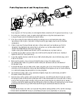
Страница 9: ... WARNING 6 Make sure the volute o ring is clean and install the large o ring in the volute groove Tip Installing the volute o ring with the volute intake port side down will ease installation of the bracket o ring 7 Assemble the motor sub assembly to the volute using the seven 7 2 3 4 hex bolts Do not tighten until all seven 7 hex bolts are in place and hand tightened then tighten all seven 7 bolt...

Страница 10: ...s If strainer pot is installed the lid may be loosened to facilitate better drainage Tip Store drain plugs and union or fitting o rings in a resealable bag and tape the bag to the pump to prevent loss 3 Once drained loosen the intake and discharge port connections 4 The pump can now be removed Be sure the pump is fully drained and if strainer pot is installed remove the lid before being stored The...

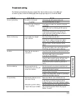
Страница 11: ...or shaft by hand to test If shaft does not freely spin replace bearings Low flow Water flow has slowed or is Clean filter basket of debris if strainer pot installed intermittent Check for impeller clog See disassembly instructions or call for details Check for leaks in volute housing lid and union connections only if strainer pot installed Check for obstructions in plumbing and clear if found Moto...

Страница 12: ...na MPS 513 PTFE Coated S S with SIC Buna MPS 517 Bracket Bracket Rear Housing in Noryl PNB 10 Bracket Rear Housing in Polypropylene PPB 10 Drain Plug Noryl Drain Plug with O Ring 1 PND 20 Polypropylene Drain Plug with O Ring 1 PPD 10 Hardware Washers and Nuts Set of Stainless Steel Hardware includes 2 3 4 Bolts 1 Bolts MPH 20 Volute O Ring Volute O Ring PBO 10 Includes 2 Drain plug o rings 1 Brack...

Страница 13: ...Performance Data 13 PERFORM ANCE ...

Страница 14: ... how long an implied warranty lasts so in such States and except as is otherwise provided by applicable law of said States no action on a warranty implied at law shall be commenced more than one year following the date of purchase No action shall be brought for breach of any express warranty subsequent to the expiration of the express written warranty 7 Incidental and consequential damages specifi...

Страница 15: ...reduced service life of your pump Protect your pump motor from the elements today Excellent weather protection Noise abatement Easy to assemble Sturdy construction Customizable precut knockout sections Fits Artesian Artesian 2 ArtesianPro and Cascade series MPC 10 14 15 15 Part ...

Отзывы: