


2
0
2
0
-1
1
32
Operation and communication
7.2
Operating with event markers
In numerous position coding system applications, defined processes must be started at spe-
cific positions so that the controller can evaluate the position data measured by the reading
head. However, this means that the exact positions for triggering events of this kind must be
defined as early as the system planning stage and can no longer be modified during the con-
struction phase or commissioning. If modifications are made, the position data stored in the
control software must be adapted accordingly, which involves a great deal of time and effort.
Activating a process through the detection of so-called event markers is a much more flexible
method. Only a specific event and the process linked with the event have to be programmed
into the system controller. The position in which the corresponding event marker is placed
along the code strip can be decided immediately before final commissioning of the system.
Even if subsequent changes are made to the layout of a system, the relevant event marker is
simply moved to the new position without requiring program modifications.
Event markers are short code strips one meter in length. The event marker bears the encoded
event number and position information in incremental form. Event markers are available with
event numbers from 001 to 999. To transfer the exact position data, the reading head calculates
the last absolute position of the code strip before it entered the event range and adds the incre-
mental offset from the codes of the event markers.
When the reading head enters the range of an event marker, it sets an event flag in the output
data. You also have the option of triggering a defined action when an event occurs by parame-
terizing one of the outputs accordingly (see chapter 7.1). Actions of this type can be initiated
when a certain event, all events or events from an event list occur.
The 1 meter long event marker can be shortened. However, the minimum length should be 30
mm (3 codes). If the travel speed of the reading head increases, a longer event marker is
required. If the reading head travels at maximum speed, a full length event marker of 1 meter
must be positioned over the code strip.
The minimum length of an event marker can be calculated according to the following formula
depending on the travel speed and the trigger period:
L
Event marker
= 30 mm + V
max
[m/s] * T
trigger
[s] x 2
With auto trigger, the trigger period is 0.025 s.
Example calculation
At a speed of 3 m/s and with a trigger period of 25 ms, the minimum length of the event marker
is therefore:
L
Event marker
= 30 mm +3 m/s * 0.025 s * 2 =
180 mm
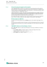
The printed event number and the inverted text identify event markers in contrast to the identifi-
cation on code strips (white text on a black background).
The illustration shows part of the event marker #127
Refer to the Accessories chapter for order information relating to event markers.
Note
When placing an event marker on the code strip, make sure that the event marker represents
an accurate continuation of the grid on the code strip where possible.


