2
0
2
0
-1
1
18
Installation
Shielding Cables
The shielding of connection lines is required to suppress electromagnetic interference. Estab-
lishing a low resistance or low impedance connection with the protective conductor or equipo-
tential bonding circuit is a particularly important factor in ensuring that these interference
currents do not become a source of interference themselves. Only use connection lines with
braid. Avoid connection lines with foil shield because this would increase the line capacities.
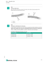
The shielding is integrated at both ends, i.e., in the switch cabinet or on the PLC,
and
on the
read head. The grounding terminal available as an accessory allows easy integration in the
equipotential bonding circuit.
In exceptional cases, the shielding of a connection at one end may be more favorable if:
•
An equipotential bonding cable is not laid or cannot be laid.
•
A film shield is used.
The following points relating to shielding must be noted:
•
Use metal cable clips that cover large areas of the shielding.
•
Place the cable shield onto the equipotential bonding rail immediately on entering the
switch cabinet.
•
Direct the protective grounding connections to a common point in a star configuration.
•
The cross-section of the cables used for grounding should be as large as possible.
Additional Ground Connection
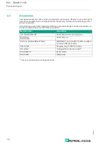
Model number
Description
PCV-SC12
Clip for mounting an additional ground con-
nection.
PCV-SC12A
Caution!
Damage to the device
Connecting an alternating current or excessive supply voltage can damage the device or cause
the device to malfunction.
Electrical connections with reversed polarity can damage the device or cause the device to
malfunction.
Connect the device to direct current (DC). Ensure that the supply voltage rating is within the
specified device range. Ensure that the connecting wires on the female cordset are connected
correctly.


