background image

INJECTOR FLOW DATA

TR18755 Rev B

30 • 

FLECK

 7000 NXT Service Manual

Содержание Fleck 7000 NXT

Страница 1: ...FLECK 7000 NXT SERVICE MANUAL...

Страница 2: ...System installation requires information from a number of suppliers not known at the time of manufacture This product should be installed by a plumbing professional This unit is designed to be install...

Страница 3: ...and place the control valve on the tank 6 All soldering MUST be done on any connections requiring soldering prior to connecting the main control valve The main control valve will be damaged if it is c...

Страница 4: ...cted to the 24 VAC Bypass Relay terminal strip on the lower left portion of the NXT circuit board Figure 6 7000NXT Circuit Board Plastic solenoid operated diaphragm valves are sold separately from the...

Страница 5: ...re 3 Interlocked Multiple Tank Alternating Systems Systems 5 and 9 BRINE TANK RESIN TANK DRAIN LINE INLET OUTLET BALL VALVE OUTLET SHUTOFF SOLENOID OPERATED DIAPHRAGM VALVE BRINE LINE BALL VALVE INLET...

Страница 6: ...peration During Programming The timer enters the Program Mode in Standby or Service Mode as long as it is not in regeneration While in the Program Mode the timer continues to operate normally monitori...

Страница 7: ...will display on the screen when flow is going through the meter TIMER DISPLAY SCREEN EXAMPLES 1 In Service System 4 Time Clock 4 SRV 03 45PM REGEN IN 07 DAYS 2 In Service System 4 Flow Meter Initiate...

Страница 8: ...c c c c c c c c c c c c Chemical Pump x x x x x x u u x x x x CPO Aux Relay Volume c c c c c c c c c c c c 1 999 gallons 00 1 99 9 liters CPO Aux Relay Time c c c c c c c c c c c c 00 00 01 02 00 00 0...

Страница 9: ...NOTE In U S Gallons mode the display will be in 12 hour time Example Grains Default Example 00 Default Filter Iron Filter Do Not Use Options 00 06 00 Default Range 1 second to 99 minutes 1 hour 39 min...

Страница 10: ...s some displays cannot be viewed or set Entering Master Programming Mode 1 Press and hold the Shift and Up buttons for 5 seconds OR 2 Set the time of day display to 12 01 PM or 12 01HR See the Setting...

Страница 11: ...ing 1 Use Up or Down buttons to adjust this value 2 Press the Extra Cycle button 9 Unit Capacity This program selects the individual timer s total capacity of hardness that can be removed The unit cap...

Страница 12: ...uring Regeneration only The second turns the output On during Service only every time a set volume of water used has accumulated MASTER PROGRAMMING GUIDE continued 16 Timed Auxiliary Relay Output Wind...

Страница 13: ...this value 3 Press the Extra Cycle button 20 Pulses per Gallon Liter This program step sets the pulses per gallon liter for generic flow meters 1 Press the Shift button to select the digit you want to...

Страница 14: ...n Press the Shift Up and Down buttons to move the cursor and change the value of the numbers Press the Extra Cycle button to proceed to the next step 5 Regeneration Time Press the Shift Up and Down bu...

Страница 15: ...zer The total volume of treated water that passes through a meter will be counted NOTE The user cannot edit below the current volume remaining 1 Reset to zero by holding the Up and Down arrow keys for...

Страница 16: ...w Phil Rd Hd 6 32 x 5 16 12 1 12473 Screw Hex Wsh 10 24 x 5 8 13 2 11805 Screw Rd Hd 4 40 x 5 8 Type 1 14 1 61920 01 Transformer Assy 7000NXT 40VA US 61920 02 Transformer Assy 7000NXT 40VA Japan 61920...

Страница 17: ...mblies 10 1 61XXX DLFC Assemblies 11 1 43776 O ring 021 7000 CSTM 12 2 13302 01 O ring 014 560CD 13 1 40946 Clip Brine Retaining 14 1 40945 Clip Drain Retaining 15 1 40950 Screen Injector 7000 16 1 40...

Страница 18: ...y 1 1 4 NPT w O ring 40565 11 Connector Assy 1 1 4 BSP w O ring 3 2 41242 01 Connector Assy 1 1 4 Sweat w O ring 41243 01 Connector Assy 1 1 4 1 1 2 Sweat w O ring 4 2 40576 Clip H Plastic 7000 5 1 40...

Страница 19: ...em No QTY Part No Description 1 1 60014 Safety Brine Valve Assy 2310 2 1 60068 30 Float Assy 2310 w 30 Rod 3 1 60002 34 Air Check 500 2310 SAFETY BRINE VALVE 42112 Rev A FLECK 7000 NXT Service Manual...

Страница 20: ...ce the error condition is corrected all units return to the operating status they were in prior to the error and regeneration is queued according to the normal system operation If reprogramming the un...

Страница 21: ...re the units on the network are not configured the same as 1 the Lead unit Exceed Unit Size DETECTED ERROR EXCEED UNIT SIZE 1 There are more units on the system than the Lead is programmed for Matchin...

Страница 22: ...Check for dry well condition Improperly sized drain line flow control Check for proper drain rate Iron in conditioned water Fouled mineral bed Check backwash brine draw and brine tank fill Increase f...

Страница 23: ...WATER CONDITIONER FLOW DIAGRAMS In Service Position 40988 Rev A 41121 Rev A Backwash Position 40988 Rev A 41121 Rev A FLECK 7000 NXT Service Manual 23...

Страница 24: ...Brine Position 40988 Rev A 41121 Rev A WATER CONDITIONER FLOW DIAGRAMS continued Slow Rinse Position 40988 Rev A 41121 Rev A 24 FLECK 7000 NXT Service Manual...

Страница 25: ...Second Backwash Position 40988 Rev A 41121 Rev A WATER CONDITIONER FLOW DIAGRAMS continued Rapid Rinse Position 40988 Rev A 41121 Rev A FLECK 7000 NXT Service Manual 25...

Страница 26: ...ver turn the cycle cam counter clockwise to the position shown in the illustration above 3 Remove brine cam if equipped 4 Slightly pull the two tabs outward and push the gearbox slightly upward to rem...

Страница 27: ...A Figure 10 After the circuit board is installed 1 Connect the motor wires to the motor connector on the circuit board 2 Connect the transformer cable to the transformer connector on the circuit board...

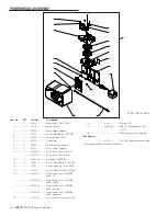
Страница 28: ...DIMENSIONAL DRAWINGS 61500 7000XTR LNE Rev A 28 FLECK 7000 NXT Service Manual...

Страница 29: ...METER FLOW DATA TR18753 Softener TR18688 Filter 41140 02 Rev A 7000NXT VALVE FLECK 7000 NXT Service Manual 29...

Страница 30: ...INJECTOR FLOW DATA TR18755 Rev B 30 FLECK 7000 NXT Service Manual...

Страница 31: ...3 5 GPM 61455 40 DLFC 3 4 4 0 GPM 61455 45 DLFC 3 4 4 5 GPM 61455 50 DLFC 3 4 5 0 GPM 61455 60 DLFC 3 4 6 0 GPM 61455 70 DLFC 3 4 7 0 GPM 61456 00 DLFC 1 Blank 61456 8 0 DLFC 1 8 0 GPM 61456 9 0 DLFC...

Страница 32: ...rks and logos are the property of their respective owners Because we are continuously improving our products and services Pentair reserves the right to change specifications without prior notice Penta...

Отзывы: