Pentair 6TS 6

6


PN524 (08-01-20)

INSTALLATION

ROTATION CHECK (3-PHASE ONLY)

After satisfactorily completing continuity test, connect cable 
to pump controller. Check 3-phase motors for correct rotation. 
If necessary, reverse any two cable leads at the controller 
and recheck rotation. Permanently mark and match to control 
box terminals for future reference. Connect cable to motor 
controller and then wire controller to disconnect switch. 
Connect temporary jumper wire between proper terminals in 
controller to temporarily energize magnetic coil. 

Momentarily engage disconnect switch and note direction of 
rotation. The shaft should rotate counterclockwise when viewed 
from the top or shaft end of the motor. If rotation is incorrect, 
reverse any two wires; mark wires to correspond with the 
controller terminal numbers.

NOTICE:


Pump is water lubricated. Do not operate the pump for 

more than 5 seconds while it is out of water.

GENERAL INSTALLATION

After completing all connections and tests so far, connect a 
5-foot length of pipe to pump.

Lower pump into well with pipe clamps attached to the 5-foot 
pipe. Attach a standard length of pipe to 5-foot length and lower 
pump CAREFULLY into well.

NOTICE:


Do not use a pipe longer than 5 feet for the first  

con nection. Hoisting pump upright with a long length of pipe can 
cause pump misalignment from excessive leverage.


CAUTION


Use extreme care when lowering pump and cable 

to avoid damage to cable insulation.

Anchor power cable to pipe every 20 feet with adjustable steel 
band clamps. Protect insulation from clamps with pieces of split 
rubber hose inserted between clamps and cable. Attach cable to 
pipe halfway between clamps with waterproof tape (Scotch No. 
33 or equivalent).

SUBMERGENCE

Be sure the pump is always submerged, even at extreme 
pumping rates. Install pump at least 10 to 20 feet below the 
lowest “drawdown” water level and at least 5 feet above bottom 
of well.

CHECK VALVES

Pump back spin and hydraulic shock can cause severe damage 
to  the pump and motor. Install at least one check valve in the 
discharge pipe (riser pipe) to help prevent this.

Install the first check valve in the pump discharge or in the 
discharge pipe it self, not more than 25’ above the pump. Install 
another check valve not more than 200 feet above the first one. 
Repeat, all the way up the riser pipe. The last check valve on the 

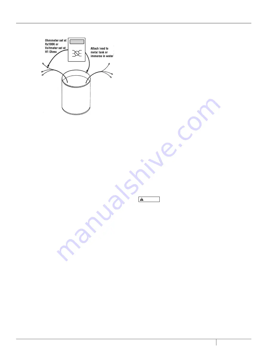
Figure 1C: Splice and Cable Continuity

SPLICE AND CABLE CONTINUITY TEST

Before installing pump check cable and splices as follows       
(see Figure 1C):

1.  Submerge cable and splice in steel barrel filled with water. 

Make sure both ends of cable are out of water.

2.  Clip one ohmmeter lead to barrel. Test each lead in cable 

successively by connecting the other ohmmeter lead to the 
three cable leads, one after the other.

3.  If resistance reading goes to zero on any cable lead, a 

leak to ground is present. Pull splice out of water. If meter 
reading changes to “infinity” (no reading) the leak is in the 
splice.

4.  If leak is not in splice, slowly pull cable out of water until 

reading changes to “infinity”. Reading will change to 
“infinity” when leak comes out of water.

5.  Repair cable by splicing as explained under “Electrical 

Splices and Connections”.

Содержание 6TS 6"

Страница 1: ...pentair com INSTALLATIONAND OPERATIONMANUAL PN524 08 01 20 2020 Pentair All Rights Reserved MODEL6TS6 SUBMERSIBLETURBINES ...

Страница 2: ...2 PN524 08 01 20 TABLEOFCONTENTS Safety Information 3 Installation 4 8 Service 9 12 Parts List 13 Troubleshooting 14 Warranty 15 ...

Страница 3: ...and local codes and ordinances Consult your local building inspector for code information GENERAL SAFETY Risk of explosion The pump body may explode if used to boost pressure above the pressures noted on Page 3 Do not use this pump with inlet pressure greater than 70 psi 483 kPa or less than 3 psi 20 7 kPa If not already in the piping system install a pressure relief valve in the pump discharge li...

Страница 4: ... deep enough to cover the pump unit with water even at extreme pumping rates Typically the pump should be submerged 10 to 20 feet below the lowest water level and at least 5 feet above the bottom of the well Air entrained in the water reduces performance and will dam age the pump Your pump is designed to provide maximum efficiency under specific capacity and head conditions Do not oper ate it beyo...

Страница 5: ...pump to reduce flow past shell Table V Cooling Flow Rates Past Submersible Motors Figure 1A Cable Splicing Solid Wire Stranded Wire Figure 1B Stagger Splices and Tape Prepare the cable and make the mechanical connections Figure 1A and splices as follows 1 Cut motor leads and corresponding cable ends at 3 inch spacings to stagger connections for a smooth splice 2 Cut connecting cable to match the m...

Страница 6: ...djustable steel band clamps Protect insulation from clamps with pieces of split rubber hose inserted between clamps and cable Attach cable to pipe halfway between clamps with waterproof tape Scotch No 33 or equivalent SUBMERGENCE Be sure the pump is always submerged even at extreme pumping rates Install pump at least 10 to 20 feet below the lowest drawdown water level and at least 5 feet above bot...

Страница 7: ...n blow the pump off the riser pipe WELL AND PUMP TEST Check and record static water level of well before starting tests Before making final piping connections test flow rate capacity and condition of well NOTICE Do not operate pump with discharge valve closed Operate pump only within pressure and flow limits of operating range established by performance curve NOTICE If sand is present in discharge...

Страница 8: ... C For each hookup find current value farthest from aver age Calculate the greatest current difference from the average Hookup 1 Hookup 2 Hookup 3 Amps Amps Amps Amps Amps Amps Amps Amps Amps D Divide this difference by the average to obtain the percentage of unbalance Hookup 1 x100 Hookup 2 x100 Hookup 3 x100 Use hookup with smallest percentage unbalance Figure 3 Voltage Test VOLTAGE TEST FIGURE ...

Страница 9: ...ed pump from well for cleaning To prevent pump from locking again when reinstalled clean the well thoroughly before reinstalling the pump SERVICE CLEANING SANDLOCKED PUMP 1 Insert a reducing bushing in discharge adapter cap to receive a hose coupling 2 Use a hose to flush pump backwards discharge to suction Oscillate shaft backwards and forwards with a pump pliers and backwash pump for several min...

Страница 10: ...ump from well and repair unit NOTICE Be sure to include cable and winding resistance Multiply cable length by the per foot cable resistance see Table IV Page 2 and add winding resistance from motor chart to get total GROUND CHECK FIGURE 6 1 Shut off main power supply and disconnect motor wires 2 Attach one ohmmeter lead to pipe or METAL well casing and the other lead in turn to each individual mot...

Страница 11: ...Stage Spacer Follow it with another Stage Spacer 13 Repeat steps 8 10 11 and 12 until you have installed all the intermediate stages You do not need to repeat the axial clearance check at every stage 14 Slide the last Impeller over the Shaft until it rests on the Stage Spacer Follow it with the Discharge Shaft Spacer and the Bearing Journal Key Nos 7 and 6 DISASSEMBLY MIXED FLOW Please refer to th...

Страница 12: ... If voltage is more than 110 or less than 90 of rated voltage consult power company SERVICE 15 Put the Rotor Compression Washer Key No 5 on the Discharge Spacer and lock it with the Rotor Compression Capscrew Key No 4 NOTE Use Loctite Threadlocker on the capscrew threads 16 Slide the Top Bowl over the shaft and seat it 17 Install the Check Valve Poppet on top of the last Bowl 18 Install the Discha...

Страница 13: ...on Washer 1 6 Bearing Journal 1 7 Dishcharge Shaft Spacer 1 8 Impeller 9 Bowl w Diffuser 10 Stage Spacer 11 Distance Sleeve 1 12 Stainless Washer 1 13 Fiber Washer 1 14 Thrust Washer 1 15 Thrust Shaft Spacer 1 KEY DESCRIPTION QTY 16 Strap Nut 4 17 Lock Washer 4 18 Strap Capscrew 4 19 Inlet Shaft Spacer 1 20 First Stage Adapter 1 21 Strap 4 22 Cable Guard Bracket 2 23 Cable Guard 1 24 Suction Scree...

Страница 14: ...circuit breaker tripped 2 Voltage does not reach terminals 3 Loose wire in control box 4 Defective magnetic controller coil 1 Reset circuit breakers or replace fuses 2 3 Phase Check voltage at controller between wire pairs L1 L3 L3 L2 L2 L1 Single Phase Check voltage between L1 and L2 on box terminal strip 3 Check and tighten all wires 4 Check starter and coil Pump does not shut off 1 Cable leads ...

Страница 15: ...e protected by three leg ambient compensated extra quick trip overload relays of the recommended size or the warranty is void All impeller diameters specified in the BEC2 pump sizing program have been tested and determined to not exceed the service factor of the specified motor Oversized impeller diameters can be requested however use of an oversized impeller will void any warranty claims Your onl...

Страница 16: ...ty of their respective owners Because we are continuously improving our products and services Pentair reserves the right to change specifications without prior notice Pentair is an equal opportunity employer P524 08 01 2020 2020 Pentair All Rights Reserved 293 Wright Street Delavan WI 53115 Ph 888 237 5353 Orders Fax 800 321 8793 pentair com ...

Отзывы: