


5
PN524 (08-01-20)
6. Repeat Step 5 for each lead.
7. Taping splice (Figure 1B):
CAUTION
Because friction tape is not water resistant,
never use friction tape on a water-tight splice. Use Scotch
Number 33, or equivalent.
7A. Clean joints and adjoining cable/wire insulation of all
grease and dirt, and build up joint area with tape until it
matches diameter of cable.
7B. Starting 1-1/2” back from the joint, firmly apply one layer
of tape, overlapping about half the previous lap and
continuing approximately 1-1/2” beyond joint. Cut tape
evenly and press both ends firmly against cable.
7C. Apply two additional layers of tape, as described in Step 7B,
beginning and ending 1-1/2” beyond the previous starting/
ending points.
INSTALLATION
FORMULA TO FIND FLOW RATE:
FPS =
GPM x .409
D1
2
– D2
2
D1 = Casing inside diameter
D2 = Motor outside diameter
CASING
SIZE
GPM
20
40
60
80
100
120
140
160
180
200
220
240
6” ID
1.2
2.3
3.5
4.6
5.8
7.0
8.0
9.3
10.4
11.6
12.7
13.9
FPS
8” ID
-
0.5
0.7
0.9
1.2
1.4
1.6
1.9
2.1
2.3
2.6
2.8
10” ID
-
-
0.3
0.5
0.6
0.7
0.8
0.9
1.0
1.1
1.3
1.4
}
NOTICE:
If flow rate past motor is expected to be less than rate shown in table, install a shroud around motor to force cooling flow past shell. To minimize
erosion to shell if flow rate is expected to be more than 10 FPS (especially if sand is present), reduce flow through pump to reduce flow past shell.
Table V:Cooling Flow Rates Past Submersible Motors
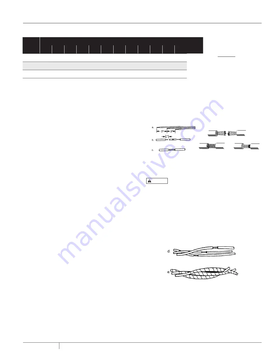
Figure 1A: Cable Splicing: Solid Wire, Stranded Wire
Figure 1B: Stagger Splices and Tape
Prepare the cable and make the mechanical connections
(Figure 1A) and splices as follows:
1.
Cut motor leads and corresponding cable ends at 3-inch
spacings to stagger connections for a smooth splice.
2. Cut connecting cable to match the motor leads.
NOTICE:
Match color coded wires, red to red, black to
black, and white to white.
3. When using a butt connector, expose bare wire for about
1/2”. When using stranded wire, expose about 1” of wire.
NOTICE:
Butt connectors may be used with solid wires
through 8 AWG, or stranded wires through 10 AWG.
4. Clean exposed ends of wire thoroughly with emery cloth
or sandpaper to assure good electrical connections.
5A. BUTT CONNECTORS (Figure 1A): Insert wires into con nector
until insulation butts up against connector. Crimp connector
to wires with a pair of crimping pliers. Pull on cable to make
sure the connection is solid and tight.
5B. SOLDERED CONNECTIONS (Figure 1A):
NOTICE: Do not use acid core solder or corrosive solder paste.
I.
Straighten individual cable strands and spread apart
slightly.
II. Clean each strand and push strands of cable into matching
(color-coded) open strands of the motor leads.
III. Wrap entire length of joint with fine copper wire until
strands are compressed.
IV. Apply heat and solder. Solder will follow the heat; make sure
solder flows throughout the joint. Pull firmly on cable to
test joint.