IntelliComm II Interface Adapter Installation and User’s Guide
Installation and User’s Guide
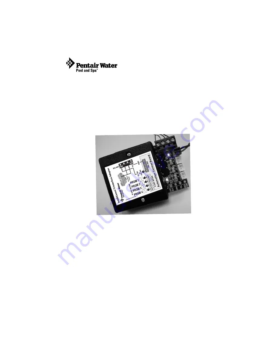
IntelliComm
®
II
Interface Adapter
(For use with IntelliFlo
®
and IntelliPro
®
pumps)
IMPORTANT SAFETY INSTRUCTIONS
READ AND FOLLOW ALL
INSTRUCTIONS
SAVE THESE INSTRUCTIONS
24 VDC
9 -


