5
required), the cord cap should be re-
attached reversing the steps above.
Ensure the o-ring is in place and
perform a hi-pot test for safety once
everything is complete.
Heat Sensors and Seal Failure
Connections:
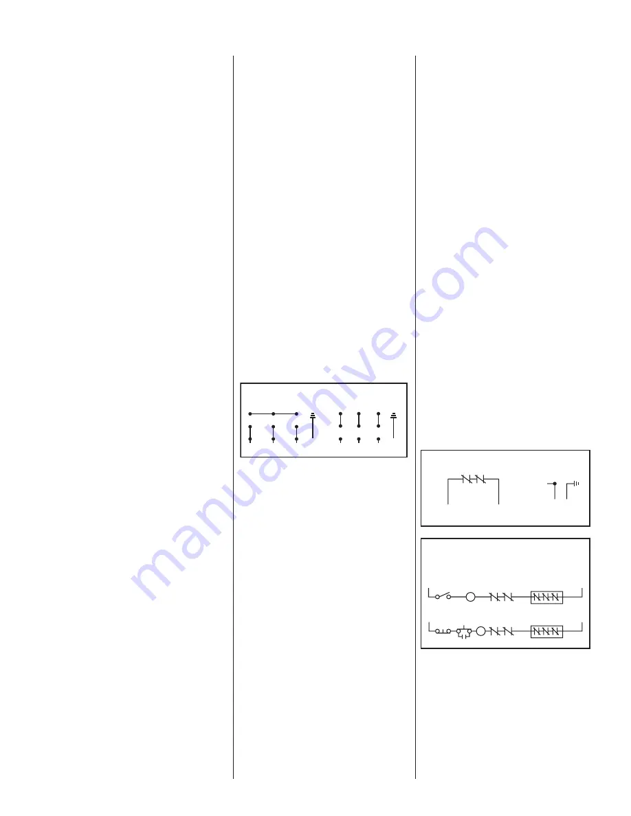
Be sure heat sensor wires are
con nect ed in series with the starter
coil. Connections are provided on
the terminal strip.
If seal failure unit is used, connect
as shown with seal failure system. If
seal failure unit is not used, the two
seal failure wires are left open.
Do not connect power to these lines
at any time.
Pump Operations
Starting System:
1. Turn H-O-A switch to Off
position and then turn on
main circuit breakers.
2. Open all discharge valves and
allow water to rise in sump.
3. Turn H-O-A switch to Hand
position on one pump and
notice operation. If pump is
noisy and vibrates, rotation
is wrong. To change rotation,
interchange any two line
leads to motor 3ø only. Do not
interchange main incoming
lines. If duplex system,
check second pump in the
same manner.
4. Now set both H-O-A switches
to Auto position and allow
water to rise in sump until one
pump starts. Allow pump to
op er ate until level drops to
turnoff point.
5. Allow sump level to rise to
start other pump. Notice run
lights on panel. Pumps should
alternate on each successive
cycle of op er a tion.
6. Turn both H-O-A switches
to Off position and allow
sump to fill to the override
control level.
7. Turn both switches to Auto
po si tion and both pumps
should start and operate
together until level drops to
turnoff point.
8. Repeat this operation cycle
sev er al times before leaving
the job.
9. Check voltage when pumps
are operating and check the
amp draw of each pump.
Check amps on each wire,
as sometimes a high leg
will exist. One leg can be
somewhat higher (5 to 10%)
without causing trouble.
For excessive amp draw on
one leg, the power company
should be con sult ed.
Phase Converters:
Phase converters are generally
not recommended, but in cases
where only single phase current
is available, phase converters can
be used. Be sure to size the phase
converter large enough for the
amp draw specified on the motor
nameplate, not necessarily by motor
horsepower. The warranty on all
three phase submersible motors is
void if operated with single phase
power through a phase converter,
and 3 leg ambient compensated
extra quick trip overload protectors
are not used.
Pump Maintenance
Lubrication or other maintenance
is not required, as the motors are
oil filled.
If a seal failure unit is used, no at ten-
tion is necessary as long as the seal
shows satisfactory operation.
If seal failure is not used, the pump
should be lifted once every two years
and the oil drained from the seal
chamber to check for water.
Lightning:
In some areas where considerable
lightning occurs, it is recommended
that a lightning arrestor be installed
at the control panel. Lightning
arrestors are good insurance against
damage to an expensive motor.
Field Service on Motor:
All submersible motors out of
warranty can be serviced in the
field by any reliable motor service
shop. Any pump (in warranty) must
be returned to the factory for
service or re paired at an authorized
Hydromatic
®
service center. Charges
will not be allowed if (in warranty)
pump is not taken to an authorized
Hydromatic service center.
When field service is performed on a
pump, these instructions should be
carefully followed.
Field Service on Hydromatic
®
Hazardous Location Pumps:
If a Hydromatic hazardous location
pump is used in a hazardous
location, or if the pump is still in war-
ran ty, the pump must be returned to
the factory for service or repaired
DUAL VOLTAGE
3 PHASE MOTOR WIRING
230V 3ø
460V 3ø
GREEN
GREEN
R
(L3)
W
(L2)
BL
(L1)
R
(L3)
W
(L2)
BL
(L1)
1
2
3
7
8
9
4
5
6
1
2
3
7
8
9
4
5
6
HEAT SENSORS AND SEAL FAILURE CONNECTIONS
FOR ANY VOLTAGE MOTOR
ELECTRODE
HEAT SENSORS
IN MOTOR
WINDINGS
WHITE
BLACK
HEAT SENSORS
SEAL FAILURE
RED
DARK
GREEN
WARNING
BLACK
COIL
ON-OFF
SWITCH
L1
THERMOSTATS
IN SERIES
WHITE
L2
TWO WIRE CONTROL OFFERING AUTOMATIC RESET
THERMOSTATS
IN SERIES
WHITE
L2
BLACK
THREE WIRE CONTROL OFFERING AUTOMATIC RESET
L1
COIL OL
OL
START
IN CERTAIN APPLICATIONS THE NEC MAY REQUIRE THREE OVERLOAD RELAYS
WARRANTY IS VOID IF HEAT SENSORS ARE NOT
CONNECTED AS SHOWN (IN SERIES WITH CONTACTOR OIL)
Содержание S3R
Страница 9: ...9 Wiring Diagrams...


