5
E-03-558 (07-05-20)
INSTALLING PUMP IN SUMP
Before installing the pump in the sump, lay it on its side and rotate
impeller. Impeller may be slightly stuck due to factory test water.
The impeller should turn freely.
DO NOT
connect the power until
after this test.
Clean all debris from sump and connect pump to piping. A check
valve must be installed on each pump and a gate or plug valve
in each pump discharge is highly recommended. This valve
should be installed on the discharge side of the check valve so
if it becomes necessary to service the check valve, the line
pressure can be cut off. Single pump systems are sometimes
installed without a check valve where it is desirable to self-drain
the discharge line to prevent freezing. This can be done only with
short discharge lines; otherwise water will return to the sump and
cause short cycling of the pump.
MAKING ELECTRICAL CONNECTIONS
All electrical wiring must be in accordance with local codes,
and only competent electricians should make the installations.
Complete wiring diagrams are glued to the inside cover of the
panel. It is VERY IMPORTANT to check all wires for grounds with
an ohmmeter or Megger(r) after the connections are made
as
one grounded wire can cause considerable trouble
.
IMPORTANT:
If equipment is not properly wired and protected as
recommended, the warranty is void.
The 230 volt 3 phase pump has a dual marked
nameplate. For ordinary location pumps, voltage may be rewired
by qualified personnel. For hazardous location pumps, voltage
may be rewired by the manufacturer or a Class I, Div I equipment
qualified electrician. Once the voltage is changed, the factory
cord tag indicating 230 volt 3 phase must be removed.
For record keeping purposes, we suggest the pump be marked
externally with the new voltage and qualified personnel that
performed the change. Pumps shipped from the factory as 460
volt 3 phase cannot be rewired to any other voltage.
TO RE-WIRE THE PUMP FROM 230V TO 460V 3 PHASE
Only a 230V pump from the factory is considered dual voltage, a
cord label clearly states the factory wound voltage.
1. Remove all six (#7) cap screws then raise the cord cap
assembly enough to slip a prying instrument on opposite
sides between the cord cap casting and the motor housing.
Take care to not damage the o-ring or the machined
surfaces of the castings. Doing so could void FM agency
certifications.
2. While prying evenly on both sides; separate the cord cap
casting from the motor housing, the assembly is airtight
and will have a vacuum effect when disassembling.
3. Once separated, the cord cap can be inverted and rotated
to the outside of the pump assembly, and a bolt can be
re-used to secure the upside down cord cap to the motor
housing for ease of rewiring.
Refer to the wiring diagram within this manual for wiring
details. Once all electrical connections are finished and secure
(a crimped electrical connector is best to prevent issues due
to vibration if required), the cord cap should be re-attached
reversing the steps above. Ensure the o-ring is in place and
perform a hi-pot test for safety once everything is complete.
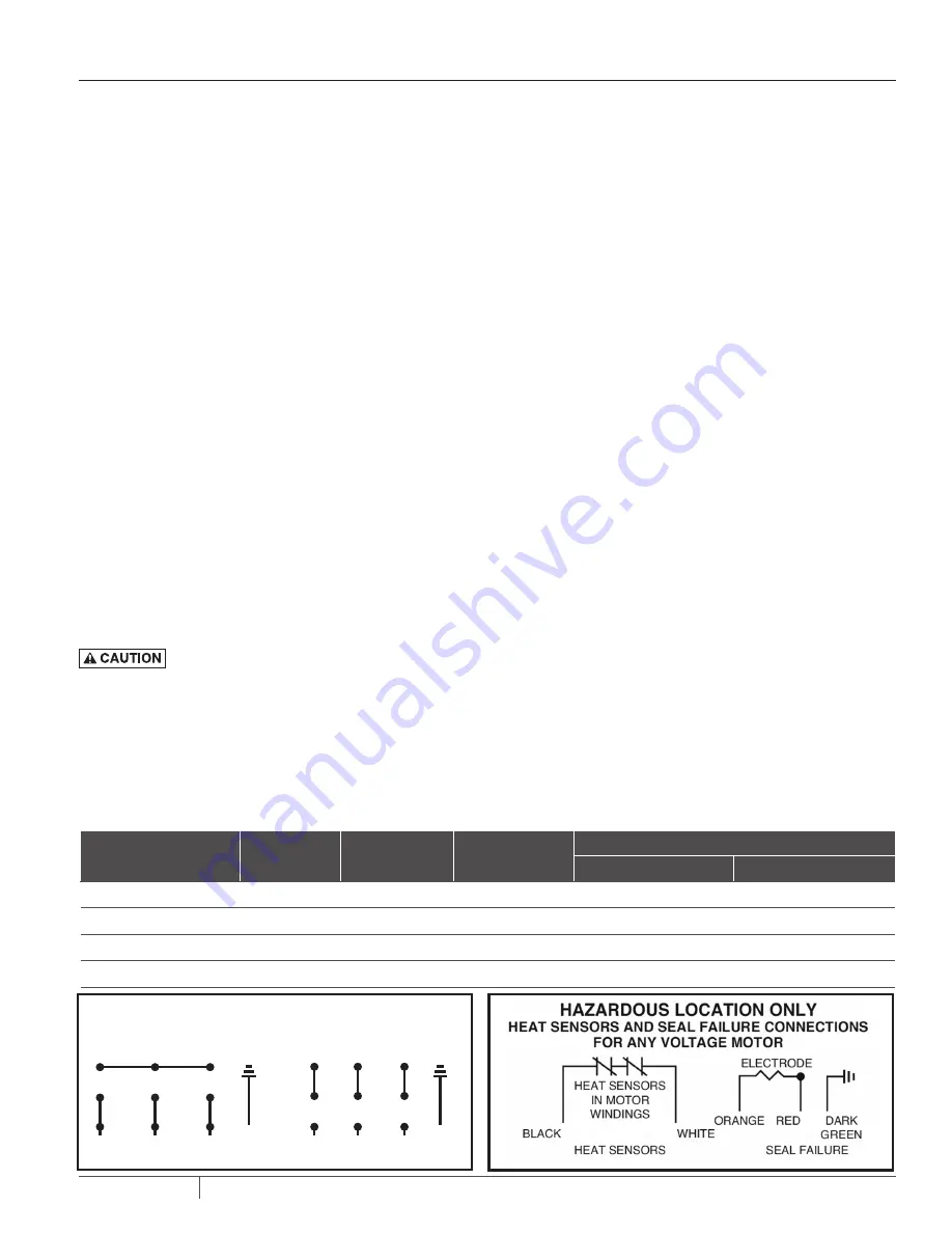
HEAT SENSORS AND SEAL FAILURE CONNECTIONS
Be sure heat sensor wires are connected in series with the starter
coil. Connections are provided on the terminal strip.
PUMP INSTALLATION
System Type
Number of
Control Wire
Number of
Power Line
Number of
Ground Wires #8
Heat Sensor & Seal Failure
Number of Sensor Wires
Number of Ground Wires
Simplex
4
3
1
3
1
Simplex with Alarm
6
3
1
3
1
Duplex
6
6
2
6
2
Duplex with Alarm
8
6
2
6
2
NUMBER OF CONDUCTORS REQUIRED BETWEEN CONTROL PANEL AND NEMA 4 JUNCTION BOX
Power lines and control wires can be carried in conduit or can be underground buried cable
DUAL VOLTAGE
3 PHASE MOTOR WIRING
230V 3ø
460V 3ø
GREEN
GREEN
R
(L3)
W
(L2)
BL
(L1)
R
(L3)
W
(L2)
BL
(L1)
1
2
3
7
8
9
4
5
6
1
2
3
7
8
9
4
5
6
ELECTRODE RESISTANCE 330
kΩ
Содержание C4H(X)P
Страница 15: ...15 E 03 558 07 05 20 WIRINGDIAGRAMS ...


