


Window Kit Installation
it may be necessary for
you to improvise/modify some aspects of the
installation procedures for certain types of
windows.
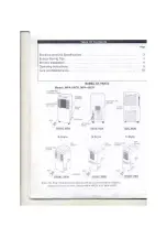
Your window kit has been designed to fit most
standard "vertical"and "horizontal" window
applications. However,
Please refer to Fig. 2 & Fig. 2a for
minimum and maximum window openings.
Before Starting This Unit
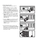
Flexible Exhaust Hose
Adjustable Window Slider Kit
NOTE: Step 2 is required only while using the
AIR CONDITIONER MODE
DO NOT USE AN EXTENSION CORD.
Water Tank
I/O
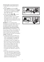
1) Select a suitable location, making sure you have
easy access to an electrical outlet.
2) Install the
and the
as depicted in
Fig. 3 & Fig. 3a.
3) Plug the unit into a 115V/60Hz grounded
electrical outlet.
4) Make sure the
is correctly positioned
inside the cabinet otherwise the unit will not
operate. Fig 4.
5) To turn the unit on, press the
key
(On/ Off Switch).
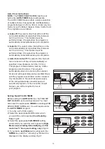
Water Tank Safety Feature
FULL
8 BEEPS
WATER FULL
This unit is equipped with a fail-safe switch
mechanism which prevents the unit from condensing
water in the event the water tank is accidentally
displaced, and/or
with water. If this situation
occurs, the unit will signal
and the
indicator light will flash red
continuously until the water tank is correctly
positioned and/or emptied.
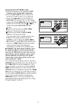
NOTE: The fan motor will continue to operate
under this condition. This is normal, but no
cooling or dehumidifying will occur until the tank
is emptied and/or correctly installed (It may take
several minutes before the compressor resumes
normal operation).
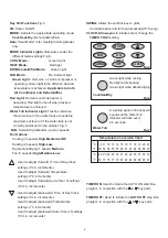
Window Installation
Window Slider Kit
Minimum:
Maximum:
26 / "(67.5 cm )
48 / "(123cm)
5
3
8
8
Window Slider Kit
Minimum: 26 / "(67.5 cm )
Maximum: 48 / "(123cm)
5
3
8
8
Horizontal Window
Vertical
Window
Fig. 2
5
Fig. 3
Fig. 3a
Fig. 2a
Fig. 4


