Keep the work area clean. Use compressed air to
remove dust hose (the dust is due to the accumula-
tion of friction welding hose), to ensure wire stabi-
lity.
When Welding, try to keep the torch cable straight.
Frequent cleaning inside the nozzle should be
done.
Use welding wire of good quality.
Installation
EXTREMIG 180 semi-automatic gas welding enclo-
sure protection class IP21S. When welding work
must not be less than 12.5mm diameter of a finger
or rod (especially metal rod) and is inserted into
the welder without pressure.
It must be well grounded; grounding wire must not
be removed before the end of the welding work
does not use welder. Otherwise, electric shock may
occur, resulting in personal injury. When the num-
ber of welding machines and other electrical equip-
ment or share a grounding device must be used in
parallel, prohibiting the use of a series.
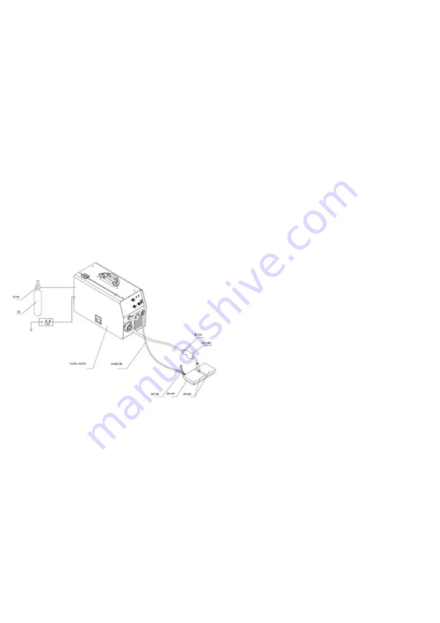
Welding connection diagram
Connection to power
-The user must connect the 4-pin power cable in
the back of welding machine to the power outlet
with breaker.
-The user must confirm that the power supply
voltage is consistent with the voltage in the name-
plate on the welding machine.
-The earth cable of the power outlet must be groun-
ded.
-Power supply configuration of single welding
machine
Air switch A ≥ 40
Power cable mm2 ≥ 2.5
Connecting the gas system
- Install the gas cylinder and tighten, make sure it
does not leak.
- Check the pressure gauge on the heater flow
regulation plug wire so that it is inserted to the
corresponding heater outlet.
-The random annex trachea, one end of the meter
outlet connection, the other end of the wire feeder
is connected to the intake pipe fittings, tighten with
hose clamps on each end.
Install the wire system in the connection
- After suitable wire diameter is selected according
to the welding process selection, please note wire
wheels wire diameter and wire feeder. Check the
guide wire tube, hose wire torch tip specifications
in order to match.
- Unscrew the wire feeder, sleeve shaft cover plate,
the plate wire into the wire feeder wire axis. Note:
Wire spools are supposed to go in a downward
direction against the wire feeder.
The disk wire within the sleeve is provided with
damping tightening mechanism (unscrew the
hexagonal screw shaft cover visible), while pulling
the wire by hand Coarse disc. Adjust damping bolt
clockwise to increase, decrease and vice versa.
Please complete the adjustment shaft cover tighte-
ned.
Import feed welding wire tube by pressing the wire
wheel.
Connecting the welding wire feed system
Connect the cable to plug into the current output
welder front panel below the ” +” socket and tigh-
ten the plug. In the other end of the wire feeder and
the rear end of the socket tighten to secure the
connection.
The 6 -core control cables were connected to both
ends of the plug at the bottom of the front panel
6-pin socket welding wire feeder and the rear end
of the 7 -pin socket and tighten.
Connection with the torch
The torch wire feeder connector into the front panel
of the interface gun and tighten.
The connection of the workpiece
The quick connector accessories supplied groun-
ding cable into the right side of the front panel with
the bottom welder ”-” the socket identity and clock-
wise to tighten, not loose, the other end clamped
workpiece.
Note: When the welding work is completed or you
temporarily leave the workspace, the welder should
be turned off on the power switch and gas valve
aswell.
welder should wear canvas overalls and welding
masks to prevent the arc light and heat.
Содержание 513875
Страница 1: ...MIG 180 MIG 180 Item No 513875...
Страница 6: ...Fels kning Huvudkretsschema...
Страница 7: ......
Страница 12: ...Troubleshooting Common weld defects...
Страница 13: ......
Страница 14: ...Verktygsboden Erfilux AB K llb cksrydsgatan 1 SE 507 42 Bor s Verktygsboden Bor s Sweden 0120504 03...


