background image

28

IPMTB-GS Motherboard Reference Guide

Boot

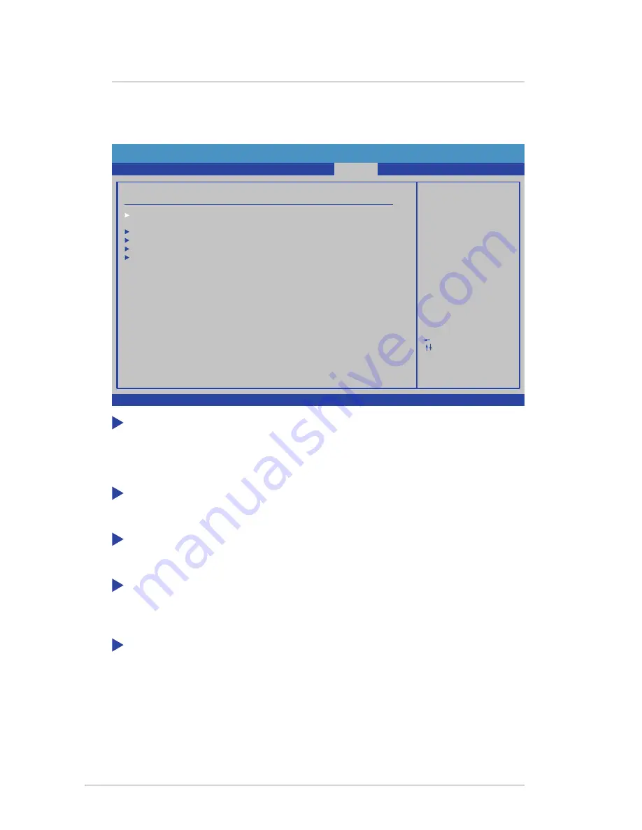
The Boot menu items allow you to view or change your boot device features. 

BIOS SETUP UTILITY

Boot Settings Configuration

Main

Boot

Exit

Configure Settings
during System Boot.

F1

Select  Screen

Select  Item

Go to Sub Screen

General Help

Save and Exit

F10

Exit

ESC

Enter

Boot Setting Configuration

Security

Power

Advanced

v02.61  (C) Copyright 1985-2008, American Megatrends, Inc.

Boot Device Priority
Hard Disk Drives
Removable Devices
CD/DVD Drives

 Boot Settings Configuration 

The items in this menu allow you to view or change the boot device settings.

 Boot Device Priority

The items in this menu allow you to view or change the priority of boot devices.

 Hard Disk Drives

The items in this menu allow you to view or change the hard disk devices settings.

 Removable Drives

The items in this menu allow you to view or change the removable devices 

settings.

 CD/DVD Drives

The items in this menu allow you to view or change the CD/DVD devices settings.

8  BIOS Setup reference

Содержание IPMTB-GS

Страница 1: ...IPMTB GS Motherboard Reference Guide ...

Страница 2: ...nectors 7 3 Central Processing Unit CPU 8 Installling the CPU 8 Installling the CPU heatsink and fan 10 Uninstalling the CPU heatsink and fan 11 4 System memory 12 Memory types 12 Memory module rules and configurations 12 Installing a DIMM 14 Removing a DIMM 14 5 Expansion slots 15 Installing an expansion card 15 6 Selectors 16 7 Connectors 17 8 BIOS Setup reference 23 Main 23 Advanced 24 Power 25...

Страница 3: ...quipment does cause harmful interference to radio or television reception which can be determined by turning the equipment off and on the user is encouraged to try to correct the interference by one or more of the following measures Reorient or relocate the receiving antenna Increase the separation between the equipment and receiver Connect the equipment to an outlet on a circuit different from th...

Страница 4: ...tact your local power company If the power supply is broken do not try to fix it by yourself Contact a qualified service technician or your retailer Operation safety Before installing the motherboard and adding devices on it carefully read all the manuals that came with the package Before using the product make sure all cables are correctly connected and the power cables are not damaged If you det...

Страница 5: ...SATA ports USB 10x USB 2 0 ports 6 onboard 4 on rear panel 1394 Via VT6315N Rear panel I O ports 1x SPDIF output port 2x eSATA ports optional 1x 1394 port 2x USB ports 1x LAN port 2x USB ports 6x Audio ports Internal connectors 1x ATX power connector 1x ATX 12V power connector 1x CPU fan connector 1x System fan connector 1x Chassis fan connector 1x Line In connector optional 1x Front panel audio c...

Страница 6: ...r in the bag that came with the component Before you install or remove any component ensure that the ATX power supply is switched off or the power cord is detached from the power supply Failure to do so may cause severe damage to the motherboard peripherals and or components Before you install the motherboard study the configuration of your chassis to ensure that the motherboard fits into it Make ...

Страница 7: ...T2 CPU_FAN F_AUDIO F_LINE_IN BATTERY BUZZER USB connector CMOS PW IEEE1394 connector F_1394 intel LGA1366 CPU Socket North Bridge Clear CMOS password Audio line in connector optional ROM_RECOVERY F_PANEL F_USB3 F_USB2 F_USB4 SATA4 top top bottom SATA3 SATA2 bottom SATA1 ATXPWR SATA connectors PCIE X16 SLOT1 PCIE X16 SLOT2 DIMM2 DIMM1 DIMM4 DIMM3 DIMM6 DIMM5 South Bridge Internal SPDIF connector PC...

Страница 8: ...ocket cap is missing or if you see any damage to the socket cap socket pins motherboard components NOTE Keep the cap after installing the motherboard It is required for product returns or repairs NOTE The product warranty does not cover damage to the socket pins resulting from incorrect CPU installation removal or misplacement loss incorrect removal of the socket cap Installling the CPU 1 Locate t...

Страница 9: ...riangle mark 7 Position the CPU over the socket as shown B A 8 Close the load plate A then push the load lever B until it snaps into the retention tab Alignment key Gold triangle mark 4 Lift the load lever in the direction of the arrow A Load plate A B C 5 Lift the load plate with your thumb and forefinger B 6 Remove the socket cap from the CPU socket C 3 Central Processing Unit CPU ...

Страница 10: ...Intel certified multi directional heatsink and fan and make sure that a Thermal Interface Material is properly applied to the CPU heatsink or CPU before you install the heatsink and fan assembly NOTE Make sure each fastener is oriented as shown with the narrow groove directed outward Fastener Motherboard hole 3 When the fan and heatsink assembly is in place connect the CPU fan cable to the connect...

Страница 11: ...an assembly from the motherboard A A B B 4 Remove the heatsink and fan assembly from the motherboard 5 Rotate each fastener clockwise to reset the orientation NOTE The narrow end of the groove should point outward after resetting 1 Disconnect the CPU fan cable from the connector on the motherboard 2 Rotate each fastener counterclockwise 3 Central Processing Unit CPU ...

Страница 12: ...ed on this motherboard Memory module rules and configurations Note DIMM2 is the socket closest to the CPU and DIMM5 is the socket farthest from the CPU Memory Module Insertion Rule 1 Insert modules starting from the DIMM closest to the CPU 2 Insert 2GB modules first then 1GB modules if both are used 3 Fill each channel two sockets with modules to fully utilize triple channel performance IMPORTANT ...

Страница 13: ...e 1GB 1GB 1GB 4GB Dual 2GB 2GB 4GB Triple unbalanced 2GB 1GB 1GB 5GB Triple unbalanced 2GB 2GB 1GB 6GB Triple 2GB 2GB 2GB 7GB Triple unbalanced 1GB 2GB 2GB 2GB 8GB Triple unbalanced 2GB 2GB 2GB 2GB 9GB Triple 1GB 2GB 1GB 2GB 1GB 2GB 9GB Triple unbalanced 2GB 2GB 1GB 2GB 2GB 10GB Triple unbalanced 2GB 2GB 2GB 2GB 2GB 11GB Triple unbalanced 2GB 2GB 2GB 2GB 1GB 2GB 12GB Triple 2GB 2GB 2GB 2GB 2GB 2GB...

Страница 14: ...tward 2 Align a DIMM on the socket such that the notch on the DIMM matches the break on the socket 3 Firmly insert the DIMM into the socket until the retaining clips snap back in place and the DIMM is properly seated 1 Simultaneously press the retaining clips outward to unlock the DIMM 2 Remove the DIMM from the socket NOTE A DDR3 DIMM is keyed with a notch so that it fits in only one direction Do...

Страница 15: ...omponents To install an expansion card 1 Before installing the expansion card read the documentation that came with it and make the necessary hardware settings for the card 2 Remove the system unit cover if your motherboard is installed in a chassis 3 Remove the bracket opposite the slot that you intend to use 4 Align the card connector with the slot and press firmly until the card is completely s...

Страница 16: ...is selector allows you to clear the Real Time Clock RTC RAM in CMOS You can clear the CMOS memory of date time system setup parameters and passwords by erasing the CMOS RTC RAM data IMPORTANT Except when using this function do not remove the jumper cap from the default position or else there may be a system boot failure To erase the CMOS RTC RAM user settings 1 Turn OFF the computer and unplug the...

Страница 17: ...or may not boot up if the power is inadequate NOTE Make sure that your power supply unit PSU can provide at least the minimum power required by your system NOTE If you intent to use a PSU with 20 pin and 4 pin power plugs make sure that the 20 pin power plug can provide at least 15A on 12V and that the PSU has a minimum power rating of 350 W The system may become unstable or may not boot up if the...

Страница 18: ...ble matches the ground pin of the connector 7 Connectors CHASSIS_FAN Ground 12V Rotation SYS_FAN Ground 12V Rotation Left Audio Channel Ground Right Audio Channel Ground CD F_LINE IN Audio line in connector optional This connector allows you to receive stereo audio input from sound sources such as an optical disc drive a TV tuner or a specialized audio sound processing card ...

Страница 19: ... are for USB 2 0 ports Connect a USB module cable to any of these connectors then install the module to a slot opening at the back of the system chassis These USB connectors comply with USB 2 0 specification that supports up to 480 Mbps connection speed WARNING Never connect a 1394 cable to the USB connectors Doing so will damage the motherboard F_USB4 F_USB3 F_USB2 USB USB USB USB Ground Ground S...

Страница 20: ...NG Never connect a USB cable to the IEEE 1394 connector Doing so will damage the motherboard TPA Ground TPB 12V Ground TPA Ground TPB 12V Digital Audio connector This connector is for the S PDIF audio module to allow digital sound output Connect one end of the S PDIF audio cable to this connector and the other end to the S PDIF module may require separate purchase SPDIF_OUT2 SPDIF Out Ground ...

Страница 21: ...I_CS _R SPI_CS SPI_MOSI SPI_MISO SPI_CLK ROM_RECOVERY Front panel audio connector This connector is for a chassis mounted front panel audio I O module that supports HD Audio NOTE It is recommended that you connect a high definition front panel audio module to this connector to utilize this motherboard s high definition audio capability F_AUDIO MIC _L MIC _R LINE _R Ground Ground LINE _L LINE _RTU ...

Страница 22: ...e to this connector The IDE LED lights up or flashes when data is read from or written to the HDD ATX power button soft off button 2 pin PWRBTN This connector is for the system power button Pressing the power button turns the system on or puts the system in sleep or soft off mode depending on the BIOS settings Pressing the power switch for more than four seconds while the system is ON turns the sy...

Страница 23: ...d AMIBIOS Use ENTER TAB or SHIFT TAB to select a field Use or to configure system Time Select Screen Select Item Change Select General Help F1 Save and Exit F10 Exit ESC Tab RT Version 01 00 02 19 09 1016MB Build Date Size System Overview System Memory System Time System Date 23 15 43 Thu 01 03 2002 Boot Security Exit Power Advanced v02 61 C Copyright 1985 2008 American Megatrends Inc AMIBIOS Disp...

Страница 24: ...enabling or disabling of motherboard chipset features CPU Configuration The items in this menu show the CPU related information that the BIOS automatically detects SATA Configuration The items in this menu allow you to view or change SATA device settings Onboard Device Settings The items in this menu allow you to view or change onboard device settings Hardware Health Configuration The items in thi...

Страница 25: ...ation Suspend Mode This item allows you to select the Advanced Configuration and Power Interface ACPI state to be used for system suspend Default Auto Power On By PME This item allows you to change the Power On By PME setting Default Disabled Options Disabled Enabled Power On RTC Alarm This item allows you to change the Power On RTC Alarm setting Default Disabled Options Disabled Enabled AC Power ...

Страница 26: ...the screen shows the default Not Installed After you set a password this item shows Installed To set a Supervisor Password 1 Select the Change Supervisor Password item and press Enter 2 From the password box type a password composed of at least six letters and or numbers then press Enter 3 Confirm the password when prompted The message Password Installed appears after you successfully set your pas...

Страница 27: ...e User Password item on top of the screen shows the default Not Installed After you set a password this item shows Installed To set a User Password 1 Select the Change User Password item and press Enter 2 On the password box that appears type a password composed of at least six letters and or numbers then press Enter 3 Confirm the password when prompted The message Password Installed appears after...

Страница 28: ...egatrends Inc Boot Device Priority Hard Disk Drives Removable Devices CD DVD Drives Boot Settings Configuration The items in this menu allow you to view or change the boot device settings Boot Device Priority The items in this menu allow you to view or change the priority of boot devices Hard Disk Drives The items in this menu allow you to view or change the hard disk devices settings Removable Dr...

Страница 29: ...ion only if you do not want to save the changes that you made to the Setup program If you made changes to fields other than System Date System Time and Password the BIOS asks for a confirmation before exiting Discard Changes This option allows you to discard the selections you made and restore the previously saved values After selecting this option a confirmation appears Select Ok to discard any c...

Страница 30: ...you to load the optimal default values for each of the parameters on the Setup items When you select this option a confirmation window appears Select Yes to load the optimal default values Select Save Changes and Exit or make other changes before saving Exit 8 BIOS Setup reference ...

Отзывы: