CAUTION:
ADULT ASSEMBLY REQUIRED.
USE CARE WHEN UNPACKING AS COMPONENTS TO BE ASSEMBLED MAY POSE A SMALL PARTS/SHARP EDGE
HAZARD.
BATTERY ALREADY INSTALLED IN VEHICLE.
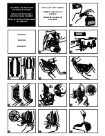
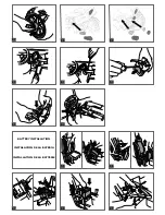
1 • Lift both rear shock absorbers and line them up with the openings in the chassis.
2 • To fasten the shock absorbers to the chassis, insert the pins into the top holes on the shocks and press firmly into place.
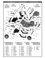
3 • Before assembling the doorway “side nets” to the “side net tubes”, check picture # 4 to establish left & right components. 8899DX = passenger side, 8899SX = drivers
side.
4 • Assemble side nets onto side net tubes by placing the thin ring onto the small middle tube extension.
5 • And place the thick ring onto large (top) tube extension. The side net should snap onto the tube contour.
6 • Picture A shows front part of side net as it is being assembled. Picture B shows side net after it has been assembled.
7 • When installed on vehicle, side net tubes should angle away from body. Place notched tube into slotted door sill hole and push forward into slot.
8 • Pull out slightly on silver body panel (1) and flex side net tube to insert small middle tube extension into the hole in the body (2).
9 • Align silver body panel by inserting small extrusion into hole in chassis.
10 •Press firmly to snap silver panel back into place.
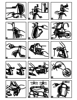
11 •Secure the profiles of the cargo box with the screws provided.
12 •Secure both sides using larger screws provided.
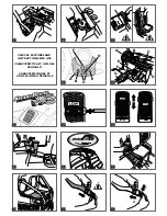
13 •Install left & right vertical roll-bar tubes into upper chassis (behind seats) and press down firmly. Note: To determine Left & Right, the “net tube” receptacle
should be away from body with the opening to the front, the upper V shaped receptacle opening should be facing the rear.
14 •Insert the top of side net tube into lower roll bar receptacle.
15 •Secure both vertical tubes using standard screw provided.
16 •Secure the side bars to the vertical tubes with screw.
17 •Assemble rear (left & right) roll bar tubes
18 •Secure top with screw.
19 •Secure bottom with screw.
20 •Assemble cross-bar brackets onto rear roll-bar tubes.
21 •Bracket opening must be horizontal, not facing upward.
22 •Assemble cross bar tube into brackets.
23 •Insert machine screw in rear hole and nut in front hole (both sides).
24 •Tighten screws.
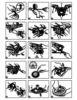
25 •On the roll-bar cross bar; you will see 3 recessed areas for the light brackets; NOTE: the wider recess (illus B) must face the rear. Place the cross bar onto the
vertical tubes.
26 •Secure seat belts (and roll-bar top) to vertical roll-bar tubes with screws (Screws are in separate hardware bag).
27 •Assemble 3 roll-bar light brackets to roll-bar with screw holes facing rear and to the top.
28 •Attach roll-bar lights to rings with screws (in hardware bag).
29 •Locate front grill and note that it has many points of attachment (A–E).
30 •Begin attaching grill by inserting tabs A and B into silver hood slots until they lock.
31 •Insert tab D into silver hood slot until it locks.
32 •Pull bottom of grill down to allow 2 square holes to fit onto 2 pegs in chassis.
33 •Assemble front bumper onto round pegs on grill.
34 •Insert bottom bumper tab into slot E in lower grill.
35 •Install screw and tighten.
36 •Secure brush guard to grill using 2 of the standard screws provided.
37 •Apply the speedometer stickers.
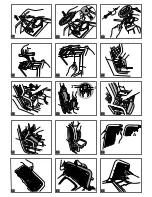
38 •Position the speedometer in the dashboard provided hole over the radio.
39 •Insert tab into left hole and press right side to lock into place.
40 •Attach red ring to steering wheel by lining up the posts with the holes and pressing.
41 •Attach black center piece to steering wheel by lining up the posts with the holes and pressing.
42 •Remove protective plastic piece from steering column.
43 •Slide steering wheel down onto column. NOTE: be sure to align holes in steering wheel with holes in steering column.
44 •Press special screw through steering wheel and steering column and secure using matching nut.
45 •Insert T-handle in square slot on passenger side.
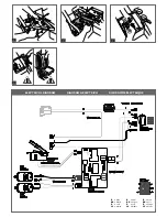
46 •Secure T-handle using standard screw provided.
47 •Snap gas cap into place on passenger’s side of vehicle.
48 •Remove thumbscrews from seat bases.
49 •Place seat onto vehicle by lining up posts on seat base with holes in seat. NOTE: seat can be adjusted for the growth of the child.
50 •Replace thumbscrews to secure seat to vehicle.
51 •Rotate seat down into place.
52 •Secure using standard screw provided.
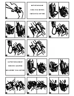
53 •Assemble windscreen. Illustration A shows it fully assembled.
54 •Secure meshes to tube with 3 screws.
55 •Place the windshield on the hood hooking the three central tabs.
56 •Secure windscreen to vehicle with screws.
57 •Install small hubcaps onto wheels.
58 •On rear bumper, apply reflective chrome decals. Then attach red plastic tail light lenses.
59 •On front, apply reflective chrome decals for headlights and fog lights. Attach clear head light lenses. For fog lights, place black plastic ring around
clear circular lenses and snap into place.
60 •Remove 2 small screws from bottom of dashboard beneath radio.
61 •Remove radio by carefully releasing tabs at top of each side.
62 •Remove small screw on battery compartment door.
63 •Insert 2 AA batteries (not included) and replace battery compartment door.
64 •Replace radio into dashboard. NOTE: be sure to place antenna wire through opening in dashboard before inserting radio. Replace screws.
BATTERY INSTALLATION
WARNING:
WARNING: BATTERY CHARGING AND ANY OTHER OPERATION ON THE ELECTRICAL SYSTEM MUST BE CARRIED
OUT BY ADULTS ONLY. THE BATTERY CAN ALSO BE CHARGED WITHOUT REMOVING IT FROM THE VEHICLE.
65 •Once battery is fully charged (light on charger is green), remove screw from passenger side seat and rotate up.
66 •Remove thumbscrews and lift seat up and out of vehicle.
67 •Remove 2 screws at front of seat base and remove seat base by lifting up and pulling out.
68 •Lower battery into compartment. NOTE: Be sure battery is setting all the way down correctly into compartment.
69 •Place battery plug through rear slot in seat base. Place vehicle wiring system plug through front slot.
70 •Replace seat base.
ASSEMBLY INSTRUCTIONS
INITIAL BATTERY CHARGE
!
• Remove battery and charger from packaging. Connect battery charger to a 120vac wall recepticle. Connect battery charger to battery.
Содержание IGOD0514
Страница 3: ...1 A SX 2 A B 12 14 13 15 16 17 18 19 20 21 22 23 24 26 25 ...
Страница 4: ...A B B D A E C B A D C E 27 28 34 38 39 35 29 30 31 32 33 36 37 40 41 ...
Страница 5: ...2 1 A 53 54 55 56 42 43 44 45 46 47 48 49 50 51 52 ...
Страница 29: ......
Страница 30: ......
Страница 31: ......


