Peerless Pump UWLLB3 Скачать руководство пользователя страница 8


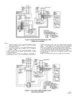
Figure 4. Single Phase Wiring Diagram, C84A or  

C93A Float Controls


NOTES: 
1. Float Control must be wired in series with P1 & P2 and  set  to  open  circuit  
when liquid level drops no lower  than  minimums  shown  on  pump dimension      
 drawings.  
2. Connect to A.C. supply line of voltage required. All wiring must be in 
accordance with N.E.C. and/or local electrical codes.  
3. Connect terminals 

7 & 8 

to remote alarm device (by others).  Terminals  

5 & 6 


can  be  wired in series with float control  to  shut  pump  down  if  moisture  is  
detected. 
 4. Combined length of control circuit leads and control wiring to moisture 
detection  control must  not  exceed 100 feet. 


5. Motors are furnished by factory with motor leads connected   for   specifies   
voltage.  If  it  is necessary  for voltage to be changed in the  field  reconnect  
terminals in  motor  terminal head in  accordance with  conversion  
diagrams.  Splices  must  be  watertight  (see  motor  instructions for further 
information). 
6. The motor warranty is valid only if moisture detection and thermal protection 
system is connected  and  operable. Failure to utilize these voids warranty. 
7. Connections to motor starter  and  disconnect  switch are  typical  only.  All  
equipment  furnished  by others is to  be  in  accordance  with  N.E.C.  and/or  
local  electrical codes. 


Figure 5. Three Phase Wiring Diagram, C84A or 

C93A Float Controls


2899213 

Содержание UWLLB3

Страница 1: ...r s factory without prior written approval Seller makes no warranty as to starting equipment electrical apparatus or other material not of its manufacture since the same are usually covered by warranties of the respective manufacturers thereof Peerless Pump Company Indianapolis IN 46207 7026 the manufacturer and may also result in bodily injury as well as property damage This book is intended to b...

Страница 2: ...ransportation company handling the shipment noting the extent of the damage or shortage on the freight bill and bill of lading Do not leave the unit exposed to weather or construction hazards The pump may become mechanically damaged This pump is a well designed and carefully manufactured and may cause personal injury Disconnect power supply before attempting to change connections in the starter Th...

Страница 3: ...g for proper rotation prior to installing pump do not run for a long period as the motor is not suitable for prolonged operation in air MOTOR ROTATION Prior to setting the pump in the basin check the direction of rotation of the motor as follows WARNING 1 Three Phase Motors a Temporarily connect motor leads to power source b Momentarily energize motor to just start turning c Observe that impeller ...

Страница 4: ...en grips to hold cables Route cables to motor control panel through conduit if required 2899213 4 D Motor cable E Packing flange F Spool piece Figure 1 Installing Sewage Pump in Basin 11 Seal the basin cover split if 2 piece basin cover was supplied manhole cover and discharge pipe flanges with a pliable non hardening sealer available at any plumbing supply PIPING The discharge pipe line of the pu...

Страница 5: ...linkage which causes MOTOR LUBRICATION No motor bearing lubrication necessary Motor bearings are sealed for life of unit alternate operation of the two pumping units The switch is controlled by the float which actuates the switch on rise and fall of the liquid level The action is such that the two switches are alternated on successive cycles If the liquid level continues to rise with one pump in o...

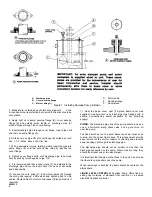
Страница 6: ...Figure 3 Installation Dimensions 6 2899213 ...

Страница 7: ...wiring i Discharge head is lower than anticipated 3 Pump Runs Continuously a Check pump rotation b See if check valve in discharge line is stuck AFTER STARTING Note the following 1 Slowly open the discharge gate valve 2 Note operation of the control mechanism Observe several complete start stop cycles of the unit See that pump control switch contacts close and open properly as basin fills and is e...

Страница 8: ...rol wiring to moisture detection control must not exceed 100 feet 5 Motors are furnished by factory with motor leads connected for specifies voltage If it is necessary for voltage to be changed in the field reconnect terminals in motor terminal head in accordance with conversion diagrams Splices must be watertight see motor instructions for further information 6 The motor warranty is valid only if...

Страница 9: ...on control in pilot controller must not exceed 100 feet 5 Motors are furnished by factory with motor lead connected for specified voltage If it is necessary for voltage to be changed in the field reconnect terminals in motor terminal head in accordance with conversion diagrams Splices must be watertight see motor instructions for further information 6 The motor warranty is valid only if moisture d...

Страница 10: ...he control and seal leakage indicator light will be de energized An influx of moisture past the outer seal and into the oil reservoir will change the conductivity of the Oil and this condition will cause the relay to energize and the seal leakage light will energize to indicate a seal leakage Load contacts 5 6 and or 7 8 will also change from their normally open or normally closed position when th...

Страница 11: ...Figure 9 Type UW Sewage Pump 11 2899213 ...

Страница 12: ...ine stone or crocus cloth 2899213 REV 4 79 When ordering replacement parts always furnish data stamped on nameplate attached to the pump Give the index number and part name as shown on figure 9 ASSEMBLY Assemble pump parts as follows see figure 9 1 Lightly oil new packing ring 15 and insert in flange 14 2 Place new gasket 13 on casing 9 install flange 14 and attach with 2 each screws 11 and nuts 1...

Отзывы: