


OPERATION
BEFORE STARTING, CHECK THE FOLLOWING
ITEMS:
1. See that voltage and frequency on motor
nameplate are the same as service provided.
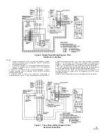
2. If motors are of the dual voltage type, be sure
motor leads are wired for the voltage used.
3. See that the proper fuses are installed.
4. See that switches are regulated for operation and
that thermal units are “set.”
STARTING:
Close the discharge gate valve and the
motor disconnect switch. The pump will not operate
unless the liquid level pilot circuit is closed. If a
selector switch is used, the pump may be run
independent of automatic controls by turning it to
“on” or manual position.
Read the list of important
Safety Precautions provided near
the front of this bulletin. The safety steps in that list
must be applied during maintenance procedures.
Failure to do so may lead to severe equipment
damage and personal injury or death.
TROUBLESHOOTING:
The following troubles may
occur. To correct trouble check for the possible
causes given.
1. Pump Fails to Operate:
a. A blown fuse, tripped or loose thermal unit.
b. Shaft binding or impeller blocked.
c. Switch contacts corroded, circuit shorted, or
terminal connections broken somewhere in circuit.
d. Pump control mechanism not functioning, or float
waterlogged.
e. Wiring hook-up or service provided incorrect, or
switches not “set” for operation.
f. Motor grounded or burned.
g. Electric service of phase failure.
h. Float rod buttons improperly adjusted or slipping.
2. Blown Fuse, Tripped Thermal Unit:
a. Fuse of thermal unit used of incorrect rating.
b. Shaft stuck or not rotating freely.
c. Loose connection somewhere in circuit.
d. Controls won of arcing.
e. Motor grounded or partially burned out.
f. Motor overloading.
g. Fuse or thermal unit location too hot.
h. Short circuit in wiring.
i. Discharge head is lower than anticipated.
3. Pump Runs Continuously:
a. Check pump rotation.
b. See if check valve in discharge line is stuck.
AFTER STARTING:
Note the following:
1. Slowly open the discharge gate valve.
2. Note operation of the control mechanism. Observe
several complete start-stop cycles of the unit. See
that pump control switch contacts close and open
properly as basin fills and is emptied by the pump.
The operation of the unit should be absolutely
automatic.
3. See that all pipe connections are tight.
4. Observe operation of pump closely for the first
day and at regular intervals for ten days. A new
machine is frequently stiff and tight, and therefore
the unit should be watched to note performance.
MAINTENANCE
c. Check discharge head, see if beyond pump rating.
WARNING
d. Check influent rate to basin; see if inflow is
excessive.
e. See if shaft in intact and if the impeller rotates.
f. Check to see if pump is air bound.
g. Check float and float switch assembly.
Tie the disconnect switch open
or
remove
fuses
from
lines
before attempting to remove pump from the basin.
Attach a card “DO NOT CLOSE SWITCH-PUMP
REPAIR IN PROGRESS.” Disregard of this warning
may result in fatal electrical shock.
WARNING
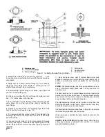
REMOVAL:
Remove the sewage pump in the
following manner (see figure 1):
1. Shut off or blank the influent line.
2. Close the gate valve in the discharge line.
3. Open the disconnect switch at power supply. Tie
switch open and attach card to prevent closing
accidentally.
4. Remove spool piece (F).
5. Loosen bolts of cover packing flange (B).
6. With an upward, twisting motion pull discharge
pipe (A) from the pump flange (E) to give clearance
for moving pump.
7. Tighten cover flange bolts to hold discharge pipe.
8. Tag leads for connection at reinstallation and
disconnect motor cables. Loosen motor cable grips
(C) and pull motor cables from cover.
9. Attach cable or sling to pump lugs and lift pump
from basin with a hoist of proper capacity.
7
2899213
Содержание UWLLB3
Страница 6: ...Figure 3 Installation Dimensions 6 2899213 ...
Страница 11: ...Figure 9 Type UW Sewage Pump 11 2899213 ...