


SECTION III
REASSEMBLY
3-1.
ROTATING ELEMENT.
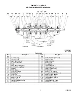
(See Figure 7 or 8). Re-
assemble as follows:
a. Coat shaft (6) with oil. Re-oil as necessary while
pressing on impellers and sleeves.
b. With grooves, square shoulder side, facing toward the
highest number stage, press inter stage sleeve (58) or
balancing disc (56) on shaft. Insert hey (128) and locate
sleeve in the center of impeller section over square key
(128); disc to engage Woodruff key (32) between fourth
and fifth stages.
c. Insert key (32), align fifth(or fourth) stage impeller
(2 or 2A) and press on outboard (inboard) end of shaft to
contact disc (56) (sleeve 58).
d. Install casing ring A (7A), or inter stage bushing (113),
insert key (32) and press on fourth (or third) stage
impeller (2 or 2A).
e. Locate casing rings (7, 7A) on impellers.
f. Position inter stage sleeves A (58A) so that grooves
will be closer to lower number stages and press on shaft
to contact impeller hubs.
g. Install inter stage bushings A (113A) over sleeves
(58A) with beveled ends toward higher stages.
h. In turn, insert remaining keys (32), align impellers in
descending order of stages and press on shaft. Install
inter stage sleeves and bushings, and casing rings
between impeller stages. Carefully bump parts to
remove all clearance so that first and second stage
impeller hubs extend equally beyond central portion of
shaft (slightly into threaded portions).
i. Install O-rings shaft sleeves (14), coat ring and shaft
with oil and screw sleeves on shaft against impeller
hubs.
j. Install the stuffing box bushing (63) and lantern ring
(29) (not used on 5-stage pumps) on the shaft.
k. Locate casing rings (7) on lowest stage impellers;
install gland flanges (17D).
l. Place water detectors (40) on shaft.
m. Slide bearing covers (35) (with oil seals (107)
installed for oil lubricated bearings) on the shaft.
n. Place shaft collars (68) on the shaft.
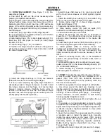
o. Mount the bearings (16) and (18) as described in
Figure No. 4. The outboard bearings are two single row
angular contact bearings mounted in the duplex DB
mounting.
p. Install bearing lock washer (69A) and locknut (22) (oil
thrower) and tighten against the outboard bearing.
q. Install gaskets (73B) on bearing covers. Cut
replacement gaskets from 1/16 inch No. 444 Vellumoid.
r. Slide the housings (31, 33) over the bearings. Tap
lightly and evenly around the end as necessary. Do not
force.
s. Attach the bearing covers (35). In the assembled
position, the grease fittings or breather tubes must be
located on top.
t. Locate water deflector (40) and tighten the setscrews.
Install oil seal (107) in the inboard bearing housing (31)
(for oil lubricated bearings).
u. Install coupling key; assemble coupling half on the
shaft and tighten the setscrew.
3-2.
PUMP
. Complete the assembly of pump as follows:
a. Use the upper casing (1B) as a template to cut a
gasket (73A) from 1/64 inch Vellumoid. Machined
surfaces of both casings must be perfectly clean and
free from burrs and nicks.
b. Affix the new gasket to lower casing (1A) with shellac.
c. Use slings around the shaft near bearings to set
rotating element into lower casing. Position the casing
rings (7, 7A), inter stage bushing (113) and both bearing
housings so that all dowel pins engage. If necessary,
loosen setscrews of water deflector to shift bearing
housings slightly. Retighten screws.
d. Assemble both bearing caps (41) and tighten the cap
screws.
e. If impellers are not (approximately) centered in volute
or impellers are not allowing case rings to seat in casing,
adjust sleeves by loosening one and tightening the other
in direction required. Tighten setscrews in sleeve after
final adjustment is made.
f. Cover the top side of the casing gasket with a mixture
of graphite and oil. Install the gland bolts. Carefully
locate the upper casing on the lower (17B), making
certain the dowel pins engage. Attach case nuts and
alternately tighten at diagonally opposite positions.
Rotate shaft by hand to check that it runs free. See
Torque Chart, Table II.
g. Withdraw the lantern rings (29) (not used on 5-stage).
9
2883819