


WARNING
Do not operate this pump at any pressure, flow rate or
liquid temperature other than those for which the pump
was originally purchased. Do not pump any other liquid
than the one for which the pump was originally purchased
WARNING
Shut down pumps. Temporarily disable the pump driver
before starting any repairs. Refer to Bulletin No. 2880549
for the procedure to follow.
1-1. Disengage the coupling halves. If pin and rubber
bushing type, remove the pins; if other type, refer to the
coupling manufacturer’s instructions. Disconnect plumbing
from water-cooled bearings.
1-2.
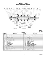
PUMP
. (See figure 1 or 2.) Disassemble pump (to the
extent required) as follows:
NOTE
Disassembly and reassembly instructions for both type
pumps are included in this bulletin. Disregard the instruct-
ions which do not apply to the specific pump being
repaired.
a. Remove the nuts from the gland bolts (17B), withdraw
gland flanges (17D) and remove glands (17) from the shaft
(6). The gland halves are separable.
b. Remove all nuts or cap screws from the upper casing
(1B) and from the bearing caps (41).
c. Screw down the jackscrews alternately and evenly to
separate the upper and lower casings. Turn the jack-
screws back after the case halves have separated to avoid
interference at reassembly.
d. Match mark and remove both bearing caps (41).
e. Attach a hoist to the eye bolts (customer furnished) or to
a sling through external cross-over to lift upper casing
(1B). Do not use eye bolts to lift pump!
f. Place slings around the shaft near the bearing housings
and lift rotating element from lower casing (1A). Tap
lightly on the underside of the bearing housings (31 and
33) to separate the housings from the brackets.
g. Place rotating element in a convenient work place.
1-3.
ROTATING ELEMENT.
Remove the plugs and drain
oil from the oil lubricated bearings. Remove constant-
level oilers (125) and pipe nipples. (Not required for
grease lubricated bearings.) Proceed as follows:
a. Loosen set screw and remove the coupling half. Tap
from the back of the hub or use a puller. Remove coupling
key (46).
b. Loosen set screws on the water deflector (40A).
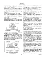
c. Remove cap screws or stud nuts from bearing covers
(35) and separate covers from housings (31) and (33).
(Use care not to damage the oil seal (107) used with oil
lubricated bearings.) See figure 3.
d. Lightly tap around housings (31,33) to remove. Do not
cock or force housings off, as to do so may damage the
2883819
without the consent of Peerless Pump Company or its
authorized representatives. Disregard of this warning can
result in pump failure and serious personal injury or death.
SECTION 1
DISASSEMBLY
bearings (16, 18), or the oil seal (107).
e. Loosen and remove bearing locknut (22 and lock
washer (69A).
f. Remove bearings as described in Figure No. 4.
g. Carefully remove shaft collars (68) (if present) and
bearing covers (35). Use care not to damage cover gasket
(73B) or oil seal (107).
NOTE
Clearance between collar and shaft is approximately 0.002
inch. Use care when removing not to cock or force, as this
will score the shaft.
h. Withdraw casing rings (7, 7A) from lowest stage
impellers. On most pumps, these may be withdrawn
before removing the coupling half.
i. Remove water deflector (40), gland flanges (17D),
packing (13), lantern rings (29) (not used on 5-stage
pump) and stuffing box bushings (63). Make note of the
number of packing rungs on each side of the lantern rings.
j. Loosen the shaft sleeve (14) set screws near impeller
hub. With a spanner wrench, turn the inboard sleeve in the
same direction as shaft rotation to remove (shaft has right-
and left-hand threads on opposite sides of impeller).
NOTE
A seal between the shaft and sleeve is made with a rubber
O-ring in a groove in the sleeve. Use care not to damage
the O-ring.
k. Support the back side of first stage impeller (2) with a
split ring on the base of a suitable arbor press. Shift the
inter stage bushing (113A) toward third stage impeller so
that support ring bears on impeller close to shaft (6).
Carefully press shaft through impeller (2).
l. Take off inter stage bushing (113A) and remove casing
ring (7) and impeller key (32).
m. Similarly support second stage impeller (2A) with split
ring, press shaft through impeller and remove key (32).
Remove casing ring (7A) and inter stage bushing (113A).
n. Support third (2) and fourth stage impellers (2A) in
same manner, press shaft through inter stage sleeve (58,
58A) and impeller, then remove keys (32).
o. Remove fifth stage impeller in the same manner.
p. Press shaft through inter stage sleeve (58) and remove
key (128), or balancing disc (56) last.
1-4.
CLEANING.
Clean all metal parts (except bearings)
with a solvent. Use a bristle brush (NOT metal or wire) to
remove tightly adhering deposits. A fiber scraper may be
used to remove the gasket and shellac from casing
flanges.
a. Blow dry with clean, dry, compressed air.
b. Clean bearings as described in 1-5.
2