


-22
-12
-30
-18
OFF
ON
PROCESS
-15
AMCL-2
Controller & Limiter
Automatic Multiband
-15
.15
-4
.25
dB
INPUT
0
-2
.2
-8
-10
-6
.4
4
6.5
sec
RELEASE
7
2.5
1
1.3
1.5
-3
LIMITING (dB)
-9
-12
-6
0
POWER
User’s Manual
AMCL2
SOUND REINFORCEMENT
ACOUSTIC RESEARCH
CONTROLLED RADIATION
7
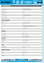
7.2 Automatic threshold corrector
The multi-band limiter divides the audio signal into different,
individually limited frequency bands and then adds them together.
The resulting level can sometimes be different from the set threshold.
With conventional methods using wideband limiters, the problem of
intermodulation distortion mentioned earlier would arise.
When using the AMCL2, by contrast, the sum of the two bands is sent
to an automatic correction circuit. If this exceeds the benchmark value,
the circuit automatically adjusts the individual thresholds of each
band. When the value falls below the benchmark level, the individual
thresholds of each band return to their original value. This way, the
sound maintains the utmost sharpness and is free of noticeable
distortions.
Finally, the AMCL2 uses a single automatic correction circuit for both
channels, providing perfect balancing of the stereo image with equal
limitation on both channels.
7 .3 Functional features
A key feature of the Automatic Multiband Controller & Limiter (AMCL2)
is that it is a
unitary gain
device, i.e. an input signal variation is matched
by an identical output signal variation. To enable the device to operate
correctly, the front panel is fitted with the following four different
controls: input level, time release and two threshold controls.
In addition, the simple design of the front panel with just a few controls
makes the AMCL2 easy to install and test. It comes complete with a
lockable front cover, as prescribed by existing regulations, to prevent
possible tampering by unauthorized users.
7 .4 Controls and functions
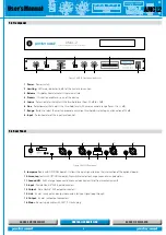
• Release time
Release time
enables the density of the music program to be altered.
It can be defined as the
interval between the time when the limiter acts
to restore the signal level and the time when the signal being processed
returns below threshold
. Differences in the duration of this parameter
cause changes in spectral characteristics.
An extremely short release time gives a very narrow dynamic range
that can cause distortion at low frequencies. By selecting a fairly
short release time, the output will be kept as close as possible to the
maximum level.
Conversely, as release time is increased, distortion will be reduced,
resulting in a softer, more rounded sound.
Finally, setting an extremely long time release will lower the average
output value, particularly if the music program contains considerable
and fast variations in level (transients).
Figure 5. Time Release selector
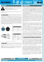
• Threshold level control
There are
three
controls to adjust the threshold level on the front panel of
the AMCL2. The first control (5 in Fig. 2), labelled COARSE, is an electronic
switch adjustable in 2 dB steps ranging from -20 dBm to +2 dBm. The
second control (6 in Fig. 2), labelled FINE, is much more precise and allows
for correction of the preceding setting with a range of action from -1 dBm
to +1 dBm. If the level of the music program to be controlled is too high
and the COARSE selector is insufficient, a third control labelled RANGE (7 in
Fig. 2) can be used to reduce the output level by 20 dB. Using these three
controls simultaneously allows you to adjust the total threshold level in a
44 dB interval.
Figure 6. Threshold selector
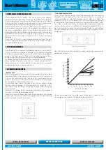
Note that the limiter can be regarded as a special compressor, representing a
compression ratio of ∞: 1.
Graph 1 Threshold effect
-15
-10
-5
0
+5
+15
+20
+10
INPUT LEVEL (dB)
)B
d(
LE
VE
L
TU
PT
U
O
-15 -10 -5
0
+5
+15 +20
+10
1:1 Unity
2:1
4:1
:1
20:1
GREE N
Below Thresh old
Rotation Point Threshol d
During device operation, the audio signal limiting level is shown by the
Limiting
(point 2 on Figure 2) LED display on the front panel.
Figure 7. Limiting display


