


-22
-12
-30
-18
OFF
ON
PROCESS
-15
AMCL-2
Controller & Limiter
Automatic Multiband
-15
.15
-4
.25
dB
INPUT
0
-2
.2
-8
-10
-6
.4
4
6.5
sec
RELEASE
7
2.5
1
1.3
1.5
-3
LIMITING (dB)
-9
-12
-6
0
POWER
User’s Manual
AMCL2
SOUND REINFORCEMENT
ACOUSTIC RESEARCH
CONTROLLED RADIATION
5
2
3
1
PUSH
1
3
2
1
3
2
2
3
1
PUSH
JUMPER CAL
LINK
INPUT
L
LINK
INPUT
R
OUTPUT
OUTPUT
L
R
PROTECTION DO NOT
REMOVE SCREW
GROUNDING
FOR CONTINUED
MAINS
230V
50/60Hz
S.N.
Lmax
Leq
1 2 3 4 5 6 7 8 9 10
off
on
16
10
13
13
12
12
15
14
15
14
11
9
-22
-12
-30
Automatic Multiband Controller & Limiter
-.6
-1
-.8
FINE
-.4
-.2
0
0dB
-20dB
THRESHOLD
RANGE
+.6
+.8
+1
+.4
+.2
(dBm)
-20
-18
-16
-12
-14
-10
COARSE
+2
-2
0
-6
-4
-8
-18
OFF
ON
PROCESS
-15
AMCL-2
AMCL-2
Controller & Limiter
Automatic Multiband
-15
.15
-4
.25
dB
INPUT
0
-2
.2
-8
-10
-6
.4
4
6.5
sec
RELEASE
7
2.5
1
1.3
1.5
-3
LIMITING (dB)
-9
-12
-6
0
POWER
VERNICIATURA: NERO OPACO
AMCL-2 _ 22-10-10
SERIGRAFIA 2 COLORI:
GRIGIO TEA HI-GLOSS
BLU PEECKER
FILE:AMCL-2_slkf.dxf
QUOTE
ANCORAGGIO
LEGENDA:
MECCANICA
COMPONENTI
SERIGRAFIA 1
H=COME DA DXF
FONT:ARIAL
Lunghezza: 435.50mm
6
5
8
3
1
7
4
2
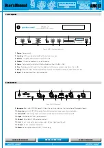
5.3 Front panel
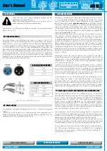
5.4 Rear Panel
1. Power
- Power switch.
2. Limiting
- LED meter indicator (in dB) of the limiter intervention.
3. Release
- This potentiometer adjusts the release time.
4. Process
- This button enables by-pass of the device.
5. Coarse
- Potentiometer
that
adjusts the threshold level from -20 dB to +2 dB.
6. Fine
- Potentiometer
that
adjusts the threshold level with a more accurate range (form -1 to +1 dB).
7. Range
- Button to select the most appropriate activation threshold by selecting an attenuation of 20 dB.
8. Input
- Potentiometer of the input level control.
9. Jumper cal
(only with OPTIONAL board) - It allows the input signal to drive the intervention of the optional board.
10. Lmax, Leq
(only with OPTIONAL board) - Dipswitch selector to change Leq and Lmax parameters.
11. Ground Lift
- Earth change to connect-disconnect electrical earth to/from mechanical earth.
12. Input
- Female Neutrik® XLR input connectors.
13. Output
- Male Neutrik® XLR output connectors.
14. Link
- 6.3 mm Jack input and output connectors for input signal loop through.
15. Output
- 6.3 mm Jack output connectors.
16. Mains
- Power supply cable with CEE 7/7
Schuko
plug
Figure 2. AMCL2 Front panel and cover
Figure 3. AMCL2 Rear panel


