Peco 50721201 Скачать руководство пользователя страница 18

18

              SECTION III

OPERATING INSTRUCTIONS

3-1  General Safety

Only qualified people familiar with this operator’s manual 
and the mower’s operator’s manual should operate this 
machine.

3-2  Operation And Tips On Mowing

A. Perform BEFORE EACH USE the maintenance list in
     paragraph 4-1.
B. Start mower.
C. With the mower at high idle speed, engage the mower 
     deck.
D. While seated in the operator’s seat, rotate the 
     engagement handle of the collection system away 
     from the mower. Continue to rotate the handle until it 
     stops in an over center position. With the blower 
     engaged, you can proceed to operate the control 
     levers of the mower.

NOTE:

 If the collection system does not appear to be 

collecting the grass clippings; disengage the deck,
and blower, engage the parking brake and turn the 
mower off. Proceed to section 3-3, and review the 
section 2-4 and 2-5, in this manual.

To obtain the maximum effectiveness from your 
collection system the tips listed below should be 
followed:

* Watch your speed- Normal conditions will allow a 
   speed of up to approximately 5 mph, but thick, heavy 
   damp conditions will require reduced ground speed.
* Mow with sharp blades- A sharp blade cuts cleaner.
* Wet grass and leaves will decrease effectiveness and 
   will increase horsepower requirements.
* Mow at higher cutting heights- Remove and mulch no 
   more than 2” of grass length with each mowing. 
   (Experts recommend not cutting off more than 1/3 of 
   the grass blade length at any given time.)
* Mow twice, at different height settings, (high, then low), 
   if grass is extra tall.
* Remember that horsepower requirements will vary with 
   the mowing conditions such as type and height of turf 
   grass, moisture content, amount of leaves, whether the 
   terrain is flat or hilly, etc.

3-3 Disengagement Of The Blower

A. To disengage the blower, rotate the engagement 
     handle towards the mower.

WARNING: 

The blower will continue to spin. DO NOT 

TOUCH the blower, pulleys, or the belt until the tractor is 
turned off. DO NOT adjust the belt tension until the 
mower is turned off. Refer to section 2-4 and 2-5 of the 
manual

3-4  Unloading The Collection System

NOTE:

 Press the tab, located behind the operator’s left 

side, downward to feel if the collection system is full. If 
the container is full there will be resistance when 
depressing the tab.

A. Stop the forward movement of the mower.
B. Disengage the mower deck.
C. Disengage the blower.
D. Verify that the dump area is clear.
E. Push the dump handle, on the left of the operator, 
     away from the unit. While holding the handle pushed 
     away, move the handle upward. The container door 
     will swing upward and the container will rotate 
     downward. The container will release its contents.
F. Once the contents of the container have fallen out, the 
     container is ready to move back into its normal 
     operating position. With the handle in the ‘away’ 
     position, pull the handle downward until it stops. 
     Move the handle towards the center of the mower. 
     This motion will allow the latch to lock back into 
     collection position.

NOTE:

 If you do not hold the handle away from the 

mower as you pull the handle downward, the latch will 
not lock and the container can unexpectedly release the 
contents collected.

SECTION IV

MAINTENANCE

4-1 Maintenance Checklist

Before each use:
1. Check blades and spindles to be sure that no foreign 
    objects, such as wire or steel strapping bands, are 
    wrapped around them.
2. Inspect blades for wear. Replace if necessary. If it is 
    necessary to sharpen the blades, remove the blades 
    from the spindles before sharpening. DO NOT 
    sharpen blades while still attached to the mower.
3. Make sure all shields are in place and in good 
    condition. Repair or replace any missing or damaged 
    shields.
4. Perform lubrication per paragraph 4-2.
5. Listen for abnormal sounds, which might indicate 
    loose parts, damaged bearings, or other damage. 
    Correct any deficiency before continuing operation.
6. With the engine off, engage the blower assembly. 
    Check the belt tension and inspect the pulley belt for 
    cracks or tears.
7. Check for wear or deterioration of the upper or lower 
    hoses. If there are any portions of the hose that have 
    been torn or worn through, replace with genuine 
    PECO parts.

After Each Use:

1. Clean all debris from machine especially from the 
    container, underneath the belt shields, and

Содержание 50721201

Страница 1: ...OPERATOR S MANUAL PTO GRASS COLLECTION SYSTEM DESIGNED FOR ASSEMBLY OPERATION MAINTENANCE MODEL 50721201 EVERRIDE WARRIOR SERIES MOWER MANUAL PART Q0351 4 00 REV 0 P PECO PECO P P P P PECO PECO PECO...

Страница 2: ...when the container is empty 11 Inspect your lawn and remove any foreign objects before mowing Never deliberately run the mower across any foreign object 12 Wear ear protection if the noise level is of...

Страница 3: ...LVED This symbol is used to call attention to safety precautions that Should be followed by the operator to avoid accidents When you see this symbol carefully read the message that follows and heed it...

Страница 4: ...ttached to PECO products are covered under a separate warranty by the respective manufacturer D UNAPPROVED ALTERATION OR MODIFICATION All obligations of PECO Inc under this warranty shall be terminate...

Страница 5: ...Once the container is full of clippings the operator can easily push and raise the lift handle releasing the container s rear door and the container will pivot towards the ground Section II INSTALLAT...

Страница 6: ...nlet clamp plates P B1668 Figure 2 1f Rotating The Donaldson Air Cleaner Note If equipped with a Donaldson air cleaner unit must be rotated to make clearance for top main frame assembly To rotate Dona...

Страница 7: ...ame leg P B0343 See Figure 2 2c 9 7 4 3 8 16 x 1 1 4 HHCS 2 3 Universal PTO Installation To mount the PTO assembly insert the mount rod on the PTO assembly P A0623 into the mounting slots located on t...

Страница 8: ...ley Figure 2 4a Figure 2 4b Top Main Frame Assembly 2 3 8 16 x 1 1 4 HHCS 2 3 8 16 Flange Nuts Per Side 2 5 Cam Assembly Adjustment The cam assembly P A0422 which controls the blower belt tension come...

Страница 9: ...lot of the handle mount bracket With the handle in place fasten the ball joint P K1442 to the end of the latch rod P A0260 Page 10 Tighten to approximately half way down the threads of the latch rod S...

Страница 10: ...10 INLET RING Figure 9 Lift Handle Assembly Figure 10 Aluminum Grass Container With Handle Attached Figure 11 Latch Hook Mechanism Assembly Figure 12 Aluminum Grass Container Assembly...

Страница 11: ...193 LINKAGE ROD J0176 LATCH SPRING J0522 HANDLE GRIP A0574 BOX HANDLE V1152 INLET RING W LOCKING PIN B8113 SCREEN B0205 BASE FRAME B1529 LATCH HOOK B0192 BASE FRAME PIVOT MOUNT K1442 ADJUSTING BALL JO...

Страница 12: ...ARDWARE BAG 1 HB0266 HARDWARE BAG A0693 WEIGHT KIT A0694 BOOT KIT 1 HB0265 ENGINE PULLEY HARDWARE BAG 1 HB0267 HARDWARE BAG 2 B0318 WEIGHT BRACKET MOUNT 1 LT 1 RT B0317 WEIGHT BRACKET 1 B0331 BOOT PLA...

Страница 13: ...xploded Parts View 28 31 30 27 29 34 35 33 8 23 24 6 32 12 2 2 2 2 2 7 7 11 21 10 1 3 3 3 3 3 3 3 3 9 4 5 15 25 25 25 25 25 25 16 16 16 16 26 22 17 17 17 17 17 17 17 17 17 17 17 17 20 20 14 13 19 18 1...

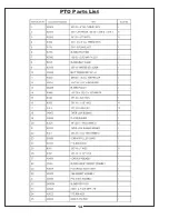
Страница 14: ...PTO Parts List 14...

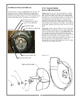
Страница 15: ...venly into the taper lock bushing forcing the blade to break away from the taper lock bushing If the impeller will not move hit the base of the impeller between each vein with a hammer then try again...

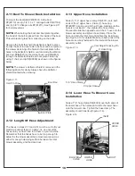
Страница 16: ...ad of the bolt is placed from the inside of the boot This will prevent grass from collecting on the bolts Remove the bolts that hold the deflector shield in place so that the boot rod can fasten the b...

Страница 17: ...elf approximately 1 to add in retaining boot to mower deck 2 16 Front Weight Installation Secure the weight brackets P B0317 to the mower by using 1 weight bracket mount P B0318 2 3 8 16 x 1 1 4 HHCS...

Страница 18: ...4 and 2 5 of the manual 3 4 Unloading The Collection System NOTE Press the tab located behind the operator s left side downward to feel if the collection system is full If the container is full there...

Страница 19: ...placement parts accessories and do any service or repairs to your collection system If for any reason your Service Center is unable to service your collection system or supply replacement parts contac...

Страница 20: ...n occur to safety decals either through shipment use or reconditioning Contact your local Service Center for replacement decals Part R1054 Part R1052 Part R1049 Part R1057 Part R1053 Part R1055 Part R...

Страница 21: ...21...
Страница 22: ...100 AIRPORT ROAD ARDEN NORTH CAROLINA 28704 800 438 5823 OR 828 684 1234 FAX 828 684 0858 EMAIL peco lawnvac com WEBSITE www lawnvac com P PECO PECO P P P P PECO PECO PECO...

Отзывы: