Peco 23651201 Скачать руководство пользователя страница 39

39

General Safety

Only qualified people familiar with this operator’s manual 
and the mower’s operator’s manual should operate this 
machine.

Operation And Tips On Mowing

A. Perform BEFORE EACH USE the maintenance list

OPERATING INSTRUCTIONS


SECTION III

     referenced in Section IV.

C. With the mower at high idle speed, engage the mower 
     deck.

D. While seated in the operator’s seat, move Bagger 
     PTO switch to the on position. With the PTO 
     assembly engaged, you can proceed to operate the 
     control levers of the mower.

NOTE: 

If the collection system does not appear to be 

collecting the grass clippings, disengage the deck
and PTO assembly, then, engage the parking brake and 
turn the mower off. Check upper and lower hoses for any 
clogs.

To obtain the maximum effectiveness from your 
collection system, the tips listed below should be 
followed:

* Watch your speed- Normal conditions will allow a 
   speed of up to approximately 4 mph, but thick, heavy 
   damp conditions will require reduced ground speed.

B. Start mower.

   if grass is extra tall.

   more than 2” of grass length with each mowing. 

* Mow with sharp blades- A sharp blade cuts cleaner.

* Mow twice, at different height settings, (high, then low), 

* Mow at higher cutting heights- Remove and mulch no 

   will increase horsepower requirements.

   the grass blade length at any given time.)

   the mowing conditions such as type and height of turf 
   grass, moisture content, amount of leaves, whether the 

   (Experts recommend not cutting off more than 1/3 of 

   terrain is flat or hilly, etc.

* Wet grass and leaves will decrease effectiveness and 

* Remember that horsepower requirements will vary with 

Disengagement Of The PTO Assembly

A. To disengage the PTO assembly, move Bagger PTO 
     switch to the off position.

WARNING: 

DO NOT TOUCH the PTO assembly, 

pulleys, or the belt until the tractor is turned off.

Unloading The Collection System

A. Stop the forward movement of the mower, engage the  

MAINTENANCE

    wrapped around them.

    necessary to sharpen the blades, remove the blades 

     will swing upward and the container will rotate 

    sharpen blades while still attached to the mower.

     away, move the handle upward. The container door 

F. Once the contents of the container have fallen out, the 

2. Inspect blades for wear. Replace if necessary. If it is 

    from the spindles before sharpening. DO NOT 

     parking brake.

D. Verify that the dump area is clear.

Maintenance Checklist

    objects, such as wire or steel strapping bands, are 

     downward. The container will release its contents.

Before each use:
1. Check blades and spindles to be sure that no foreign 

     away from the unit. While holding the handle pushed 

B. Disengage the mower deck.

C. Disengage the blower.

E. Push the dump handle, on the left of the operator, 

     container is ready to move back into its normal 
     operating position. Pull the handle downward until  


positive latching is achieved.

NOTE:

 Do not allow collection system to become over-

filled as potential damage may occur to your 
equipment. Also, be sure to clean the screen as 
needed.


SECTION IV

2019 (v1.0)

Содержание 23651201

Страница 1: ...Pro RS ProCat MX ProCat P P P PECO PECO PECO PECO PECO PECO P P P P P P P P PECO PECO R R R MANUAL PART Q0548 ASSEMBLY OPERATION MAINTENANCE PTO X DRIVEN GRASS COLLECTION SYSTEM Model 23651201 6000 Se...

Страница 2: ...Installation 19 20 General Safety 39 Lubrication 40 SECTION PAGE IV MAINTENANCE 39 40 SAFETY 4 Be especially watchful of children and pets entering into the area while operating anyone who is not acq...

Страница 3: ...G THE MOWER S ENGINE AND WAITING FOR ALL MOVING PARTS TO COME TO A COMPLETE STOP Set the parking brake Always remove the ignition key before beginning maintenance This symbol is used to call attention...

Страница 4: ...e returned to New PECO Inc at 10 Walden Drive Arden NC 28704 before any warranty adjustment can be authorized At the time of requesting warranty adjustment the purchaser must present evidence of the d...

Страница 5: ...eft front rear top or bottom are as viewed from the normal operator s position on the mower The grass collection system is designed for turf maintenance where there is a need to collect the grass clip...

Страница 6: ...The engine pulley assembly must be installed using an arbor press or equivalent During installation opposite bearing inner race must be supported or bearing damage may occur Refer to Figure D Once th...

Страница 7: ...ed Before installing your Grass Collection Unit remove the mower s rear bumper and if applicable the lower hardware securing the oil cooler Refer to Figures A and B below Figure B Predator Pro ProCat...

Страница 8: ...Below Note Some parts and features have been hidden from view for visual clarity Next position the Top Bracket Mount Arm Item 1 to the right side of the mower and align the bolt holes of the Top Brack...

Страница 9: ...1 4 Carriage Bolts Item 2 and 3 3 8 16 Ny Flange Lock Nuts Item 3 Bottom Bracket Mount Arm Installation Figure A Rear Frame Bracket Installation Position the Rear Frame Bracket Item 1 between the Left...

Страница 10: ...relatively loose Next position and align the bolt holes of the Right Main Frame Leg Item 2 to those of the Top Bracket Mount Arm Loosely secure the Right Main Frame Leg by using 2 3 8 16 x 1 Carriage...

Страница 11: ...Left Right Main Frame Legs Loosely secure the Main Frame Assy by using 2 3 8 16 x 1 Carriage Bolts Item 2 and 2 3 8 16 Ny Flange Lock Nuts Item 3 per side Refer to Figure A Once secured tighten all ha...

Страница 12: ...acket Mount Arm This will serve as a stop to help position the Receiver Tube Assy Refer to Figure A Note Some parts and features have been hidden from view for visual clarity Next place the Receiver T...

Страница 13: ...d Assembly P A2069_02 to the Drive Assembly P A2061_01 using 2 1 4 20 x 5 8 Carriage Bolts P K1010 and 2 1 4 20 Ny Flange Lock Nuts P K2014 Refer to Figure A Leave Bolts Loose Notice Marked Holes Belo...

Страница 14: ...y P A2067_02 to the Belt Guard Assembly P A2069_02 using 2 3 8 16 x 1 Carriage Bolts P K1182 and 2 3 8 16 Ny Flange Lock Nuts P K2038 Refer to Figure C D Tighten All Bolts 1 K1182 3 8 16 x 1 Carriage...

Страница 15: ...80 Belt P M0322 between the Belt Guard and the Idler Mount Assembly Place belt around the Engine Drive Pulley on the underside of the mower While one person inserts a screw driver or similar tool into...

Страница 16: ...ighten the Ball Joint to approximately half way down the threads on the Latch Rod Attach the Ball Joint to the Latch Hook as shown in Figure D using 1 5 16 24 Hex Nut P K1444 and 1 5 16 Lock Washer P...

Страница 17: ...the functionality of the dump mechanism pull the Lift Handle away from the unit and lift upward The Door of the Box Assembly should open and the Box should pivot clockwise towards the ground The mech...

Страница 18: ...e B Fasten Inlet Ring Item 1 top holes using 2 5 16 IT Tooth Lock Washers Item 4 2 5 16 18 x 1 1 4 HHCS Item 5 Slide Debris Deflector Item 2 over inside top bolt threads Item 5 Fasten Debris Deflector...

Страница 19: ...Bolt Refer to Figure D for proper Blower Cone installation reference Once the 2 bolts are tight tighten the Jam Nuts against the threaded boss as shown in Figure C Thread 1 5 16 18 Jam Nut P K0120 ont...

Страница 20: ...e C 1 Rotate Boot 45 2 Align Boot to the Discharge edge 3 Secure Boot Plate Next position the Boot Plate to the deck edge rotated at 45 1 refer to Figure C aligning the Boot Plate to the deck s discha...

Страница 21: ...e Clamp and rotating the Inlet Snap Fastener towards the hose to lock in place The hoses in the following steps must be cut to fit your Length Of Hose Adjustment Slide a Hose Clamp P J0080 over both e...

Страница 22: ...installation of the PTO Engagement Rocker Switch P P0293 Route the Positive Lead w Fuse Block to the positive terminal of the battery 3 using the Ring Terminal of the Positive Lead to secure the atta...

Страница 23: ...the Switch Mount Bracket s P B1955 slots behind the 2 bolts Tighten the 2 bolts to secure Switch Mount Bracket Refer to Figure B Place the PTO Engagement Rocker Switch P P0293 into the Switch Mount Br...

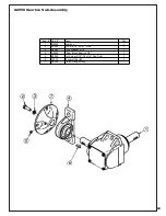
Страница 24: ...24 Wire Harness Installation Continued Figure D...

Страница 25: ...ully hit the base of the Impeller between each vein with a hammer then try again Impeller Blade Removal Replacement To Replace Place Impeller Blade over the engine shaft Slide the Taper Lock Bushing 5...

Страница 26: ...he Weight Bracket Base and the Weight Bracket Clamp assembly along the caster tubing to prevent interference from caster forks or any other objects Tighten the fasteners in an X pattern until assembly...

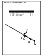
Страница 27: ...27 A2207 Mount Arm Tube Assembly...

Страница 28: ...Part Desc Qty 1 B0958_02 Idler Mnt Pl 1 2 K2038 Ny Flange Lock Nut 3 8 16 2 3 K1463 Flat Washer 720 ID x 1 500 OD x 250 T 2 4 K1219 Jam Nut 3 8 16 1 5 K1192 HHCS 3 8 16 x 1 1 4 GR5 1 6 K0329 Nylock Nu...

Страница 29: ...Gearbox 1 2 K0428 HHCS 5 16 24 x 1 GR8 1 3 K0043 Lock Washer 5 16 1 4 N0002 Pillow Block Bearing 7 8 1 5 K0035 Set Screw 5 16 18 x 1 4 Cup Point 1 6 J0272 Woodruff Key 9 1 7 A2048 Clutch Flange Assy...

Страница 30: ...nted Washer 7 16 1 375 OD x 440 ID x 179 T 1 4 K0140 Lock Washer 7 16 High Collar Helical Spring 1 5 K0359 HHCS 7 16 20 x 4 00 w Patch 1 6 M0309 A Section Pulley 4 75 OD 1 7 S0221 Eng Pulley Bushing 2...

Страница 31: ...31 Item Part Desc Qty 1 K0048 Lock Washer 3 8 4 2 K0343 HHCS 3 8 16 x 7 8 GR8 4 3 A2059_01 Clutch Sub Assy 1 4 A2058 Gearbox Sub Assy 1 A2057_01 Drive Assembly Exploded Parts View...

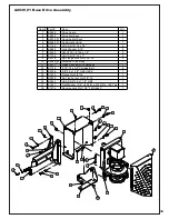
Страница 32: ...32 A2060_01 Mounted Drive Assembly...

Страница 33: ...7 K0353 HWHTCS 1 4 20 x 1 2 2 8 K1154 HHCS 5 16 18 x 1 4 9 K2516 Ny Flange Lock Nut 5 16 18 2 10 A2060_01 Mounted Drive Assy 1 11 P0271 Quick Connect Wire Harness 1 12 K1142 5 16 18 x 3 4 Carraige Bol...

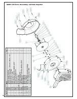
Страница 34: ...34 A2061_02 Drive Assembly 4 Blade Impeller...

Страница 35: ...35 9 7 19 11 3 3 2 10 1 14 4 12 15 16 18 17 5 6 13 8 20 21 22 22 23 24 24 25 26 26 27 28 A2100 6512 Box Assembly Exploded Parts View...

Страница 36: ...rt Desc Qty 1 B1000 Latch Rod Hook Side 1 2 K0400 1 2 Flat Washer 1 084 OD x 528 ID x 120 T 2 3 J0303 Spring 1 4 K0086 Hair Pin Clip 125 OD x 2 50 1 5 A2106 Latch Rod Weldment 1 A2107 Latch Rod Assemb...

Страница 37: ...37...

Страница 38: ...cal Service Center for replacement decals Part R1054 Important Hose Wear Part R1051 Warning Hearing Protection Part R1069 Warning Turn Off Blower Part R2007 Danger Never Use Hands Part R2008 Danger Ro...

Страница 39: ...of leaves whether the Experts recommend not cutting off more than 1 3 of terrain is flat or hilly etc Wet grass and leaves will decrease effectiveness and Remember that horsepower requirements will v...

Страница 40: ..._____________ Unit Model Number _______________________________________________ Address _________________________________ State _______ Zip _______ New PECO Inc Phone 1 800 438 5823 828 684 1234 Email...

Страница 41: ...41...

Страница 42: ...e speed Grass is too long Grass is too wet Worn belt Ground speed is too fast Collection bags are too full Loose belt Cut grass when it is dry Cut the grass several times Dump more frequently Always o...

Страница 43: ...43 Notes...

Страница 44: ...CO PECO PECO PECO PECO PECO P P P P P P P P PECO PECO R R R New PECO Inc Phone 1 800 438 5823 828 684 1234 Email peco lawnvac com 10 Walden Dr Arden North Carolina 28704 Fax 828 684 0858 Website www l...

Отзывы: