


12
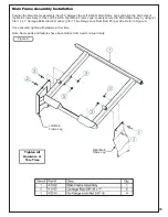
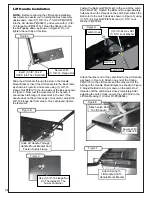
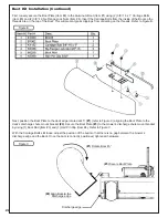
Once the Receiver Tube Assy is secured, remove the extra 3/8”-16 x 3-1/2” HHCS.
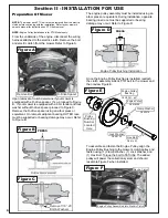
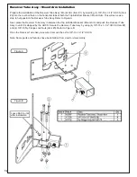
Receiver Tube Assy / Mount Arm Installation
Prepare the installation of the Receiver Tube Assy / Mount Arm (Item #1) by inserting (1) 3/8”-16 x 3-1/2” HHCS (Item
#2) into the rear bolt hole on the horizontal tabs of both the Top & Bottom Bracket / Mount Arm. This will serve as a
stop to help position the Receiver Tube Assy. Refer to Figure A.
Note: Some parts and features have been hidden from view for visual clarity.
Next, place the Receiver Tube Assy in between the Top & Bottom Bracket / Mount Arm and push the Receiver Tube
Assy in until it is stopped by the HHCS. Secure the Receiver Tube Assy by using (4) 3/8”-16 x 3-1/2” HHCS (Item #2)
and (4) 3/8”-16 Ny-Flange Lock Nuts (Item #3). Refer to Figure B.
Figure A
Figure B
Leave Bolt in until
after installation
Содержание 23651201
Страница 24: ...24 Wire Harness Installation Continued Figure D...
Страница 27: ...27 A2207 Mount Arm Tube Assembly...
Страница 32: ...32 A2060_01 Mounted Drive Assembly...
Страница 34: ...34 A2061_02 Drive Assembly 4 Blade Impeller...
Страница 37: ...37...
Страница 41: ...41...
Страница 43: ...43 Notes...