background image


PeakTech

®


1885 / 1890


Bedienungsanleitung /  

Operation manual 


Programmierbare DC-Schaltnetzteile  

mit PC-Schnittstelle /  

programmable Switching Mode Power 

Supplies with PC interface  

Содержание 1885

Страница 1: ...PeakTech 1885 1890 Bedienungsanleitung Operation manual Programmierbare DC Schaltnetzteile mit PC Schnittstelle programmable Switching Mode Power Supplies with PC interface ...

Страница 2: ...annung Strom über Tastenfeld 6 6 3 Verwenden der Programmierfunktionen 6 6 3 1 Zeitprogrammierung 6 6 3 2 Programmlauf starten 6 6 3 3 Vorprogrammierung 6 6 3 4 Auswählen der Voreinstellung 6 6 4 Einstellen des Betriebsmodus 6 6 4 1 Ausgang Ein Aus 6 6 4 2 Tastenfeld und Drehschalter sperren entsperren 6 6 4 3 Auswahl der PC Schnittstelle RS 232 RS 485 6 6 4 4 Einstellen der oberen Spannungsgrenze...

Страница 3: ...are bei RS 232 Schnittstelle 12 8 4 1 Starten der Anwendungssoftware bei RS 232 12 8 4 2 Bedienung 14 8 4 3 Data Log und Setting Fenster in der Anwendungssoftware 15 8 4 4 Das Zeitrahmenkonzept von Data Log 16 8 4 5 Internes Zeitprogramm 17 8 4 6 Interner Programmspeicher 17 8 5 Ausführen der Anwendungssoftware bei RS 485 Schnittstelle 18 8 5 1 Multi Windows Analyse 18 Anhänge Anhang A Befehlssatz...

Страница 4: ... Sicherung ersetzen Sicherung oder Sicherungshalter niemals kurzschließen Gerät Prüfleitungen und sonstiges Zubehör vor Inbetriebnahme auf eventuelle Schäden bzw blanke oder geknickte Kabel und Drähte überprüfen Im Zweifelsfalle keine Messungen vornehmen Verwenden Sie ausschließlich 4mm Sicherheitstestkabelsätze um eine einwandfreie Funktion des Gerätes zu gewährleisten Messarbeiten nur in trocken...

Страница 5: ... 10 mV Eingangsspannung 100 240 V AC 50 60 Hz Max Eingangsleistung 285 W Leistungsfaktor 0 9 Display 4 stellig Multifunktions LCD Display Strom Spannungs und Leistungsmesser Genauigkeit 1 5 Counts für Bereich V 5V I 0 5A 1 2 Counts für Bereich V 5V I 0 5A LCD Maße 48 x 66 mm Kühlung Thermostatgeregelter Lüfter Betriebstemperatur 0 40 C Schutz Überspannungsschutz Strombegrenzung Übertemperaturschut...

Страница 6: ...rungssoftware Diese Netzteil Serie erfüllt die Sicherheitsnorm EN 61010 und EN 55011 EMV für wissenschaftliche industrielle Geräte gemäß den EU Richtlinien Bewahren Sie dieses Handbuch an einem sicheren Ort auf und wenden Sie sich bei Bedarf von optionalem Zubehör für RS 485 an Ihren Händler HINWEIS Labornetzgeräte sind nicht zum Laden von Batterien konzipiert Eine solche Benutzung kann zu schwerw...

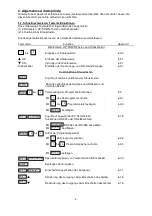
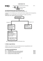
Страница 7: ...sten Zugriff auf andere Funktionen der Steuertasten Beenden aller Eingabevorgänge und Rückkehr zum normalen Betrieb bis Verwendung der Programmierfunktionen 5 2 Mit das Zeitprogramm aufrufen 6 3 1 Mit bis Programmplatz festlegen 6 3 3 Mit bestätigen Zugriff auf Auswahl der PC Schnittstelle 6 1 3 Sie können RS 232 oder RS 485 wählen Mit RS 232 oder RS 485 auswählen Mit bestätigen bis Aufruf der Pro...

Страница 8: ...as Netzteil über das Anzeigefeld bedient wird Folgende Abläufe können durchgeführt werden 6 1 Einstellen des Betriebsmodus 6 1 1 Ausgang Ein Aus Seite 5 6 1 2 Tastenfeld und Drehschalter sperren entsperren Seite 5 6 1 3 Auswahl der PC Schnittstelle RS 232 RS 485 Seite 5 6 1 4 Einstellen der oberen Spannungsgrenze Seite 5 6 1 5 Ausgang beim Einschalten Ein Aus Seite 5 5 SHIFT 0 0 ENTER Programmieru...

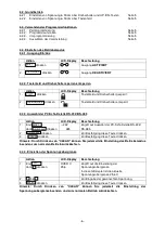
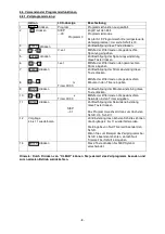
Страница 9: ...stelle RS 232 RS 485 Aktion LCD Display Beschreibung 1 Erst dann drücken 232 485 Zugriff auf Auswahl der PC Schnittstelle RS 232 RS 485 2 drücken Zur Bestätigung diese Taste drücken 3 drücken Zur Bestätigung diese Taste drücken Hinweis Durch Drücken von CLEAR können Sie jederzeit die Einstellung des Betriebsmodus beenden zum normalen Betrieb zurückkehren 6 4 4 Einstellen der Spannungsobergrenze Ak...

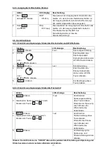
Страница 10: ...Tasten drücken 3 drücken I set Stromeinstellung 4 Drehen oder UP DN drücken Zum Einstellen des Stroms Drehschalter drehen oder UP DN Tasten drücken 5 drücken Zur Bestätigung diese Taste drücken 6 5 2 Einstellen von Spannung Strom über Tastenfeld Aktion LCD Anzeige Beschreibung 1 2 drücken Gewünschte Spannung eingeben durch Drücken der Tasten bis V set Zum Start der Spannungseinstellung diese Taste...

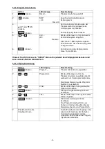
Страница 11: ... die gewünschten Minuten in den Timer eingeben 9 drücken Zur Bestätigung der Minuteneinstellung diese Taste drücken 10 bis s Timer 00 00 Mithilfe der Zifferntasten die gewünschten Sekunden in den Timer eingeben 11 drücken StEP 01 Zur Bestätigung der Sekundeneinstellung diese Taste drücken Das Programm wechselt dann zum nächsten Schritt d h Schritt 1 12 Vorgänge 4 bis 11 wiederholen Zur Einstellung...

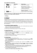
Страница 12: ...kehren 6 6 3 Vorprogrammierung Aktion LCD Display Beschreibung 1 drücken Program _ Programmierfunktion ausgewählt 2 bis Programm 4 Mit den Zifferntasten 1 9 die Programmnummer auswählen Gerät wechselt zum Vorprogrammiermodus Bei diesem Beispiel wurde Programm Nummer 4 ausgewählt 3 bis V Set Mit den Zifferntasten die gewünschte Spannung eingeben 4 drücken Die Spannungseinstellung mit Enter bestätig...

Страница 13: ... ein SDP Kalibrierungs Symbol im Programm Menü erstellt 7 1 3 Bedienungsanleitung 1 Vergewissern Sie sich dass der PC ausgeschaltet ist schließen Sie das RS 232 Kabel an den Serial Com Port Ihres PC und an das Netzteil an 2 Drücken Sie auf dem Netzteil die Taste SHIFT dann schnell die Taste RS232 485 und wählen Sie RS 232 gefolgt von ENTER 3 Schalten Sie den PC ein und lassen Sie die Kalibrierungs...

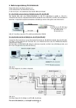
Страница 14: ...Abb 8 1 Anschluss zwischen PC und Einzelnetzteil über RS 232 8 2 Anschließen mehrerer Netzteile an den PC über RS 485 Verwenden Sie bei mehreren anzuschließenden Netzteilen die RS 485 Schnittstelle über den RS 485 Anschluss auf der Rückseite der Netzteile Bis zu 31 Netzteile können über die RS 485 Schnittstelle angeschlossen werden Sie benötigen ein RS 232 RS 485 Adapter optionales Zubehör und die...

Страница 15: ...l wird im Programm Menü erstellt 8 4 Ausführen der Anwendungssoftware bei RS 232 Schnittstelle HINWEIS Vor dem Ausführen der Anwendungssoftware muss das Netzteil auf dem PC installiert und über das RS 232 Kabel an den PC angeschlossen sein 8 4 1 Starten der Anwendungssoftware bei RS 232 1 Vergewissern Sie sich dass der PC ausgeschaltet ist schließen Sie das RS 232 Kabel an den Serial Com Port Ihre...

Страница 16: ...korrekt Das Netzteil arbeitet normal Abb 8 4 1d Abb 8 4 1e Zeigt es aber wie in Abb 8 4 1e No Connection an kontrollieren Sie Folgendes A Wechseln Sie zurück zum Setup und prüfen Sie ob der richtige COM Port zugewiesen wurde B Prüfen Sie am Netzteil ob RS 232 ausgewählt wurde C Überprüfen Sie den RS 232 Kabelanschluss D Prüfen Sie ob das Netzteil EINgeschaltet ist 13 ...

Страница 17: ... der Verwendung mehrerer Netzteile über eine RS 485 Schnittstelle zur Verfügung 2 Address Adresse Diese Funktion ist für Multi Netzteil Anwendungen Jedes Netzteil besitzt eine eindeutige Adresse Ignorieren Sie diese Funktion wenn Sie RS 232 verwenden 3 Voltage Spannung Geben Sie die gewünschte Ausgangsspannung mit Dezimalzeichen ein 4 Current Strom Geben Sie den gewünschten Ausgangsstrom mit Dezim...

Страница 18: ...it von 1 Sekunde aufwärts eingeben oder aus dem Dropdown Menü auswählen Sie können einen Spannungsobergrenzwert eingeben um Ihre Niederspannungsanwendungen weiter zu schützen 2 Data Log Fenster A Mit dem Data Log Fenster können Sie vorhandene Ausgangsmesswerte oder gespeicherte Daten anzeigen B Alle am unteren Bildschirmrand angezeigten Parameter können direkt über PC Eingabe mit Dezimalzeichen ge...

Страница 19: ...chern erfassten Daten im xls Format auf Ihren PC gespeichert 7 xls Log Datei öffnen Durch Klicken auf dieses Symbol werden die im xls Format erfassten Daten in die SDP Software importiert 8 Log Datei löschen Wenn Sie auf dieses Symbol klicken wird die aktuelle bzw aufgerufene Log Datei mit dem auf dem Display aktuell angezeigten Log Namen gelöscht 9 xls Log Datei drucken 8 4 4 Das Zeitrahmenkonzep...

Страница 20: ...ammlauf starten Betriebszyklus Geben Sie hier die Anzahl der gewünschten Betriebszyklen ein Die maximale Anzahl an Zyklen beträgt unendlich wenn 0 Zyklus eingegeben wird Betrieb 1 Löschen Sie zuerst die alten Daten auf dem Netzteil durch Klicken auf Clear Table Tabelle löschen und dann auf Save To PS Auf Netzteil speichern 2 Vergewissern Sie sich durch Klicken auf Read Fro PS Vom Netzteil lesen da...

Страница 21: ...ühren Sie das SDP Programm aus 5 Klicken Sie auf Setup und wählen Sie den gewünschten COM Port Die Standardeinstellung ist COM 1 6 Klicken Sie in der Symbolleiste auf Supply Connect und wählen Sie dann aus dem Dropdown Menü die Option Single 7 Das Internal Timed Program Fenster wird angezeigt 8 Durch Auswahl der Adresse im Adressfeld Abb 8 5a können Sie die gewünschten Einstellungen für jedes Netz...

Страница 22: ...lossenen Netzteile werden angezeigt 2 Log Aufzeichnung anzeigen Ein Klick und die Log Aufzeichnung aller angeschlossenen Netzteile wird angezeigt 3 Digital und Log Aufzeichnung anzeigen Ein Klick und sowohl die Log Aufzeichnung als auch die digitalen Messwerte aller angeschlossenen Netzteile werden angezeigt Abb 8 5 1d Sie können durch Klicken auf die Log Aufzeichnung das Netzteil auswählen Die Lo...

Страница 23: ... die Data Log Fenster Symbol Beschreibung 1 Log Datei speichern 2 Log Datei löschen Löscht die Log Daten im PC 3 In eine xls Datei exportieren Wenn Sie auf dieses Symbol klicken werden die bei Log Datei speichern erfassten Daten im xls Format auf Ihren PC gespeichert 4 Log als xls Datei öffnen Durch Klicken auf dieses Symbol werden die im xls Format erfassten Daten in die SDP Software importiert 5...

Страница 24: ...30h 39h 39h 39h 3 Byte Daten 30h 30h 39h 39h 2 Byte Daten address 30h 30h 3fh 3fh 2 Byte Daten Fett Eingabebefehl Kursiv vom Netzteil zurückgegebene Daten Befehlscode zurückgegebene Daten Beschreibung Befehl SESS address CR Daten vom Netzteil OK CR Deaktivierung des Tastenfeldes und Setzen des Geräts auf Fernbedienung Befehl ENDS address CR Daten vom Netzteil OK CR Aktivierung des Tastenfeldes und...

Страница 25: ...CR Daten vom Netzteil Memory 1 Voltage Current CR Memory 2 Voltage Current CR Memory 9 Voltage Current CR OK CR Alle voreingestellten Speicherwerte aus dem Netzteil auslesen Befehl GETM address location 1 9 CR Daten vom Netzteil Voltage Current CR OK CR Einen bestimmten Speicherplatz des Netzteils auslesen Befehl GETP address CR Daten vom Netzteil Program 00 Voltage Current Minute Second CR Progra...

Страница 26: ...annung XX X V Strom X XX V Befehl CURR address current 000 XXX CR Daten vom Netzteil OK CR Strompegel setzen Befehl SOVP address voltage 000 XXX CR Daten vom Netzteil OK CR Spannungsobergrenze des Netzteils setzen Befehl SOUT address 1 CR Daten vom Netzteil OK CR Ausgang des Netzteils ausschalten Befehl SOUT address 0 CR Daten vom Netzteil OK CR Ausgang des Netzteils einschalten Befehl POWW addres...

Страница 27: ...teil OK CR Spannungs Strom und Zeitwerte für das zeitgesteuerte Programm setzen Befehl RUNM address location 1 9 CR Daten vom Netzteil OK CR Speicherplatz aufrufen 1 9 Befehl RUNP address times 000 999 CR Daten vom Netzteil OK CR Zeitgesteuertes Programm starten 000 endlos Befehl STOP address CR Daten vom Netzteil OK CR Zeitgesteuertes Programm stoppen 24 ...

Страница 28: ...LUSSINFORMATIONEN Anhang B Informationen zu RS 232 Kabel und Anschluss Anmerkung Es wird von einem Zeilenpuffer von 16 Byte ausgegangen Das serielle asynchrone Framing Format kein Paritätsbit 8 Datenbit 1 Stoppbit Bitrate 9600 bps 25 ...

Страница 29: ...direkt an den RS232 COM Port Ihres PC angeschlossen werden STEUERUNG und PIN BELEGUNG RS 232 RS 485 Adapter 2 3 4 5 1 Abb 1 1 RS 232 Anschluss an den PC COM Port 2 RS 485 Anschluss an das Gerät mit RS 485 Schnittstelle Es gibt 6 Pins von denen nur A B und GND verwendbar sind 3 Pin A 4 Pin B 5 Pin GND TECHNISCHE DATEN RS 232 Seite des Adapters DB 9 Buchse RS 485 Seite des Adapters 3 Pin Stecker Pin...

Страница 30: ...r Art Fotokopie Mikrofilm oder ein anderes Verfahren nur mit schriftlicher Genehmigung des Herausgebers gestattet Letzter Stand bei Drucklegung Technische Änderungen des Gerätes welche dem Fortschritt dienen vorbehalten Hiermit bestätigen wir dass alle Geräte die in unseren Unterlagen genannten Spezifikationen erfüllen und werkseitig kalibriert geliefert werden Eine Wiederholung der Kalibrierung n...

Страница 31: ...e and Current Using Keypad 34 6 3 Using the Programming Features 34 6 3 1 Timed Programming 34 6 3 2 Running the Timed Program 34 6 3 3 Preset Programming 34 6 3 4 Selecting Preset 34 6 4 Setting of Operation Models 35 6 4 1 Enable Disable Output 35 6 4 2 Lock Unlock the Keypad and Jog Dial 35 6 4 3 PC Interface RS 232 RS 485 selection 35 6 4 4 Upper voltage limit setting 35 6 4 5 Output Enable Di...

Страница 32: ...RS 232 Interface 41 8 4 1 Start up the Application Software for RS 232 41 8 4 2 General Operations 43 8 4 3 Data Logging and Setting Windows in Application Software 44 8 4 4 The Time Frame Concept of Data Log 45 8 4 5 Internal Timed Program 46 8 4 6 Internal Preset Memory 46 8 5 Running the Application Software for RS 485 Interface 46 8 5 1 Multi Window Analysis 47 Appendices Appendix A Command Se...

Страница 33: ...nsulation or bare wires before connection to the equipment Please use only 4mm safety test leads to ensure immaculate function To avoid electric shock do not operate this product in wet or damp conditions Conduct measuring works only in dry clothing and rubber shoes i e on isolating mats Never touch the tips of the test leads or probe Comply with the warning labels and other info on the equipment ...

Страница 34: ...oltage limit Power Factor Correction Remote Programming Specifications Communications Interface RS 232 Single Power Supply and RS 485 up to 31 Power Supplies Remote Programming Functionality Full control of power supply functions and data readback Data Logging Yes with supplied software Baud Rate 9600bps 3 Introduction This series of Programmable Switching Mode Power Supplies are designed for full...

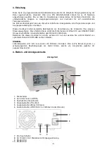
Страница 35: ...Control Key 4 Red colour positive polarity output terminal 5 Black colour negative polarity output terminal 6 Green colour ground terminal connected to chassis 7 Power Switch 8 AC 100 240 V AC Power Socket with input power fuse 9 RS 232 Port 10 RS 485 Port 32 7 8 10 9 1 4 6 5 2 3 ...

Страница 36: ...rogramming features 5 2 Use to recall the timed program 6 3 1 Use thru to specify the location of preset program to be 6 3 3 stored Use to confirm Press to enter the PC interface selection menu 6 1 3 You can choose either RS 232 or RS 485 Use to select RS 232 or RS 485 Use to confirm the settings thru Press to recall your stored preset or timed program Use to recall the timed program 6 3 2 Use thr...

Страница 37: ...PC Interface RS 232 RS 485 Selection Page 5 6 1 4 Upper Voltage Limit Setting Page 5 6 1 5 Output Enable Disable at Power Up Page 5 6 2 Basic Operation 6 2 1 Setting of Voltage and Current by Jog Wheel and UP DOWN Key Page 5 6 2 2 Setting of Voltage and Current by Key Pad Page 5 6 3 Using programming features 6 3 1 Timed Programming Page 5 6 3 2 Running the Timed Program Page 5 6 3 3 Preset Progra...

Страница 38: ...LCD Display Description 1 Press then OVER V 25 6 This will enter into upper voltage limit adjustment In this example 25 6 V is the present upper voltage limit 2 to Use this number key to input your desired voltage 3 Press Press this key to confirm Note Whenever to terminate the upper voltage limit settings press CLEAR to return to normal operation 6 4 5 Output Enable Disable at Power Up Action LCD...

Страница 39: ...rrent using Keypad Action LCD Display Description 1 2 Press Press desired voltage using numbering Keypad from to V set Press this Key to start on setting voltage Setting voltage by pressing numbers on Keypad 3 4 Press Press desired current using numbering Keypad from to I set Press this key to start on setting current Setting current by pressing number on Keypad 5 5 Press Press Enter to confirm vo...

Страница 40: ... Use the number key to input your desired minutes in the timer 9 Press Press this key to confirm the minutes setting 10 to s Timer 00 00 Use the number key to input your desired seconds in the timer 11 Press StEP 01 Press this key to confirm the seconds setting The program will then advance to the next step i e Step 1 12 Repeat Procedures 4 to 11 You can repeat procedure 4 to 11 for setting the ne...

Страница 41: ... 6 6 3 Preset Programming Action LCD Display Description 1 Press Program _ This will use the Programming Feature 2 to Program 4 Use the number key 1 9 to select the program number and it will enter into the Preset Programming Mode In this example Preset Program Number 4 is selected 3 to V Set Use the number key to input your desired voltage 4 Press Press Enter to confirm the voltage setting 5 to I...

Страница 42: ...on icon is created in the Program Menu 7 1 3 Operation Instruction 1 Ensure your PC is Off connect RS 232 to serial com port of your PC and the power supply 2 On your Power Supply press SHIFT key then quickly press RS232 485 key and select RS 232 followed by ENTER key 3 Switch on your PC and run the recalibration software 4 Follow the instructions shown in the software 7 2 Trouble Shooting 1 Keypa...

Страница 43: ...Multiple Power Supplies to PC via RS 485 For multiple power supplies use the RS 485 Interface through the RS 485 port at the rear panel of the power supply Up to 31 power supplies can be connected via RS 485 You will need a RS 232 to RS 485 adapter optional accessory and the connection shown in Figure 8 2a and 8 2b Figure 8 2b Connection diagram for multiple power supply Figure 8 2a Connection dia...

Страница 44: ... installation 3 A SDP icon is created in the Program Menu 8 4 Running the application software for RS 232 Interface NOTE Before running the application software you must have installed and connected your power supply to the PC using the provided RS 232 cable 8 4 1 Start up the Application Software for RS 232 1 Ensure your PC is OFF connect RS 232 cable to the serial port of your PC and the power s...

Страница 45: ... supply is connected to PC The power supply is operating normally Figure 8 4 1d Figure 8 4 1e If it shows No Connection as shown in Figure 8 4 1e check the following A Go back to Setup check if the correct COM port has been assigned B Check the power supply if RS 232 has been selected C Check the RS 232 cable connection D Check whether the power supply is ON 42 ...

Страница 46: ...upply in use Actually this feature is ainly for multiple power supplies application with RS 485 2 Address This function is for multiple power supplies application Each power supply has a unique address Ignore this function when using RS 232 3 Voltage Enter the desired output voltage with decimal point 4 Current Enter the desired current limit with decimal point 43 Serial No S2405000 V A ...

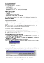
Страница 47: ...d up or select from the drop menu You can set your output voltage upper limit value to further safeguard your low voltage applications 2 Data Log Window A You can use the Data Log window to view present output data or stored data B All the parameters at the bottom of the window display can be changed by direct entry from the PC with decimal point and then confirm by the Enter key of the PC or sele...

Страница 48: ...e Log in xls format to your PC 7 Open File Log of xls type Click on this icon will import the collected data in xls format file to the SDP software 8 Delete Log Click on this icon will delete the current log or retrieved log on the display at a current Log Name 9 Print Log in xls Format 8 4 4 The Time Frame Concept of Data Log The data logging function starts when the software is started running I...

Страница 49: ... Get data from the Power Supply Run To run the Timed Program Running Cycle Enter the number of desired running cycles here The maximum cycles is infinite as 0 cycle is entered Operation 1 Clear old data in the power supply by first click Clear Table then click Save To PS 2 Check if no data in power supply by click Read Fro PS 3 Enter data in the table using the Up Down Left Right keys of your PC k...

Страница 50: ...lt is set to COM 1 6 In the tool bar Click on Supply Connect then click on Single in the drop menu 7 An Internal Timed Program Window will appear 8 By choosing the address in the Address Field Figure 8 5a You can input the desired settings for each power supply as given in Section 8 4 2a on page 20 Figure 8 5a Address of each Power Supply 8 5 1 Multi Window Analysis 1 In the tool bar Click on Supp...

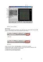
Страница 51: ...it will show the digital readings of all the connected power supplies 2 Show Log One click it will show the data log of all the connected power supplies 3 Show Digital and Log One click it will show both the data log and digital readings of all the connected power supplies Figure 8 5 1d You can click on the data log to select the power supply the data log will highlight in blue and the address bar...

Страница 52: ... Description 1 Save Log 2 Delete Log It can delete the log data in the PC 3 Export to a file of xls type Click on this icon will export the collected data in Data Log in xls format to your PC 4 Open file Log of xls type Click on this icon will import the collected data in xls format file to the SDP software 5 Close file Log of xls type Click on this icon will close the import xls format file 6 Pri...

Страница 53: ...data address 30h 30h 3fh 3fh 2 bytes data Bold Input Command Italic Return Data from Power Supply PS Power Supply Command Code Return Data Description Input Command SESS address CR Return Data from Power Supply OK CR Disable front panel keypad and make PS to Remote Mode Input Command ENDS address CR Return Data from Power Supply OK CR Enable front panel keypad and make PS to exit Remote Mode Input...

Страница 54: ... from Power Supply Memory 1 Voltage Current CR Memory 2 Voltage Current CR Memory 9 Voltage Current CR OK CR Get All Preset Memory Values from PS Input Command GETM address location 1 9 CR Return Data from Power Supply Voltage Current CR OK CR Get Memory from Specific Preset of PS Input Command GETP address CR Return Data from Power Supply Program 00 Voltage Current Minute Second CR Program 01 Vol...

Страница 55: ... CURR address current 000 XXX CR Return Data from Power Supply OK CR Set Current Level Input Command SOVP address voltage 000 XXX CR Return Data from Power Supply OK CR Set upper Voltage Limit of PS Input Command SOUT address 1 CR Return Data from Power Supply OK CR Disable Output of PS Input Command SOUT address 0 CR Return Data from Power Supply OK CR Enable Output of PS Input Command POWW addre...

Страница 56: ...OK CR Set Voltage Current and Time period of Timed Program Input Command RUNM address location 1 9 CR Return Data from Power Supply OK CR Recall Preset Memory 1 9 Input Command RUNP address times 000 256 CR Return Data from Power Supply OK CR Run Timed Program 000 run infinite times Input Command STOP address CR Return Data from Power Supply OK CR Stop Timed Program 53 ...

Страница 57: ...ND CONNECTION INFORMATION APPENDIX B RS 232 CABLE AND CONNECTORS INFORMATION Remark The line buffer is assumed to be 16 bytes long The serial asynchronous framing format no parity bit 8 data bit 1 stop bit bit rate 9600 bps 54 ...

Страница 58: ...ted to male RS 232 communication port of your PC CONTROL AND PIN ASSIGNMENT RS 232 to RS 485 Adapter 2 3 4 5 1 Fig 1 1 RS 232 Connect to the PC communication port 2 RS 485 Connect to equipment with RS 485 interface There are 6 pins only A B and GND pin are useful 3 Pin A 4 Pin B 5 Pin GND SPECIFICATIONS RS 232 side of the adapter DB 9 female connector RS 485 side of the adapter 3 pin connector Pin...

Страница 59: ...ich are in the interest of progress reserved We herewith confirm that the units are calibrated by the factory according to the specifications as per the technical specifications We recommend to calibrate the unit again after 1 year PeakTech 04 2012 th Ho PeakTech Prüf und Messtechnik GmbH Kornkamp 32 DE 22926 Ahrensburg Germany 49 0 4102 42343 44 49 0 4102 434 16 info peaktech de www peaktech de ...

Отзывы: