18
6 Installation and start-up
6.3.1 Prepare the voltage source for the DIN rail
▪
Use a power source of the following specification:
−
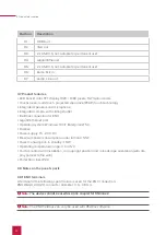
15 - 20 V DC for the control cabinet, Item number: PNX11-20007
−
Max. current: during operation: 4 A, during the PC boot process: 4.5 A (at 15 V)
▪
Disconnect the pluggable screw terminal (C1;2) from the Controlpro.
▪
Connect the cable cores of the power supply unit to it.
6.3.2 Preparing the voltage source for the flush-mounted box
Particularly, when replacing a foreign device with the Controlpro, a power supply is often
already present in the flush-mounted box. This means that mains voltage and low voltage are in
the same housing and if connected incorrectly, even parts that normally only carry low voltage
unintentionally carry mains voltage.
Warning
Avoid touching dangerous voltages in the event of a fault!
▪
Route cables so that low voltage wires are dependably protected against mains voltage.
▪
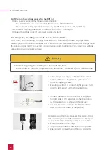
Screw the power supply unit to the flush- moun-
ted box at its mounting feet using the two sup-
plied self-tapping screws.
▪
Mounting position: at central height approx. 2 cm
from the left side of the flush-mounted box.
▪
Connect the 230 V side of the power supply to
the right side of the terminals on the Controlpro
flush-mounted box as shown in the picture.
▪
Connect the mains cable to the left side of the
luster terminal as shown in the picture.
Depending on the flush-mounted box, some- times
it is necessary to extend the 230 V side of the pow-
er supply. Use the Controlpro 230 V connection
set, also available in the shop.
▪
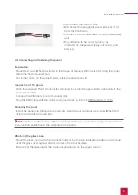
Prepare the connectors as shown in the picture.
▪
Make sure to connect the earthing at all points!
Содержание Controlpro PNX11-20001
Страница 1: ...V 2 1 1 Controlpro User manual EN...
Страница 27: ...Declaration of conformity 27...
Страница 28: ...www peaknx com...

