Brought to you by PCS Electronics, www.pcs-electronics.com
49
Appendix E: Controlling output power - ControlMini 1
Controlling output power of FM band RF amplifier is not as easy as one would think. The typical method of reducing drive
only works to a degree. Since FM band amplifiers are typically non-linear they don’t perform well when under-driven it isn’t a
good idea to control output power by adjusting the max pro 50xx+ output power only. Fortunately, there is a better way to
control output power; by changing power supply voltage. An amplifier that gives 300W at 48V will give only 50-80W at 24V.
This is really a very effective and power efficient way of controlling output power, but how can you control mains power
supply voltage with MAX PRO 50xx+ you may wonder. This is where ControlMini 1 comes into play. It was designed
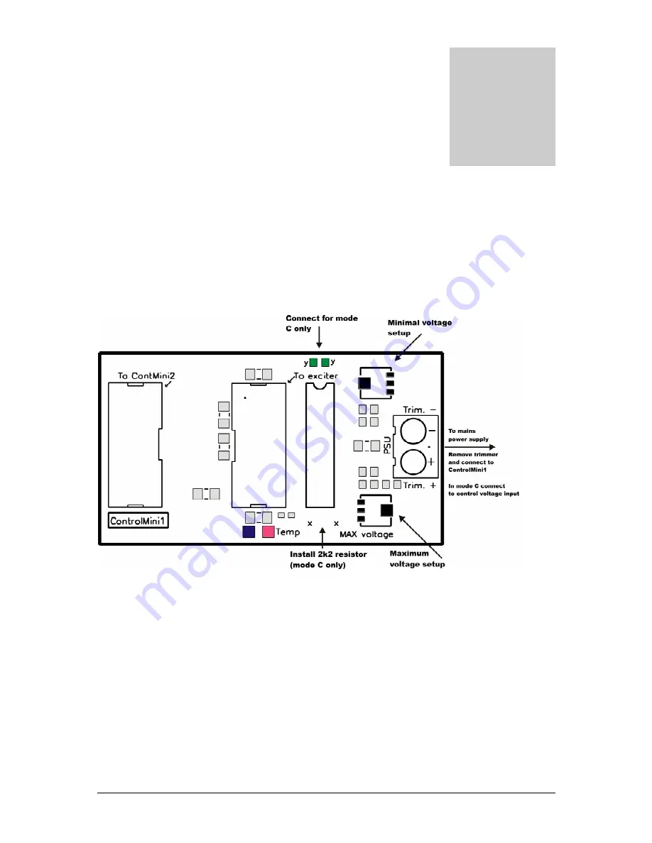
specifically for the task. Lets look at the board layout below:
Fig. 24: ControlMini1, up close and personal
How do you connect this board to the max pro 50xx+? Easy, simply just follow the markings on the board above. The first
connector goes to control board2 (if you want to use it), the second goes to max pro 50xx+. The usual Digiamp-10 flat cable
is used for both connections. There are three modes of operation:
- Mode A and B: ControlMini1 is connected in place of the trimmer, remove voltage adjustment trimmer from your mains
power supply and connect it to ControlMini1 header. Since output voltage can be proportional or inversely-proportional to
resistance of the trimmer you have two selections in the MAX PRO 50xx+ menu system, they let you select mode A or B.
If you set this wrong, you will have maximum power when you set max pro 50xx+ to zero and vice versa.
- Mode C: Some mains power supplies have a special dedicated input for controlling their output voltage. Typically 0-5V DC
voltage is used to control them. To enable this mode install a 2K2 resistor and solder a bridge across two solder pads at the
top. Now connect the output that usually goes to the trimmer to the power supplies controlling input. Select mode A or B
depending on how output voltage follows control voltage (proportional or inversely proportional).
Appendix
E


