PCI Express GRL-PCIE-TX Скачать руководство пользователя страница 8

GRL-PCIE-TX Quick Start/User Guide/MOI 


Rev1.0


© PCI-SIG 2022


                          Version 1.0, Mar 2022. Updated 03.26.2022


Page.

3


Setting Up GRL-PCIE-TX Automation Software 

This section provides the procedures to start up and pre-configure the GRL-PCIE-TX automation 
software before running tests. It also helps users familiarize themselves with the basic operation 
of the software

Note: The GRL-PCIE-TX software installer will automatically create shortcuts in the Desktop and 
Start Menu when installing the software.  

To start using the GRL-PCIE-TX software, follow the procedures in the following sections. 

3.1


Download GRL-PCIE-TX Software 

Download and install the GRL-PCIE-TX software as follows: 
1.


If the GRL-PCIE-TX 

software is to be installed on a PC (where is referred to as ‘controller PC’), 

install VISA (Virtual Instrument Software Architecture) on to the PC where the GRL software is 
to be used (see Section 2.2).  

2.


Download the software ZIP file package from the Granite River Labs support site. 

3.


The ZIP file contains: 


PCIETxTestApplicationxxxxxxxxxxxxSetup.exe


 Run this on the PC or on the 

oscilloscope to install the GRL-PCIE-TX application. 


PCIe4_TxTestScopeSetupFilesInstallationxxxxxxxxxSetup.exe


 Run this on the 

oscilloscope to install the scope setup files. 

3.2


Launch and Set Up GRL-PCIE-TX Software  
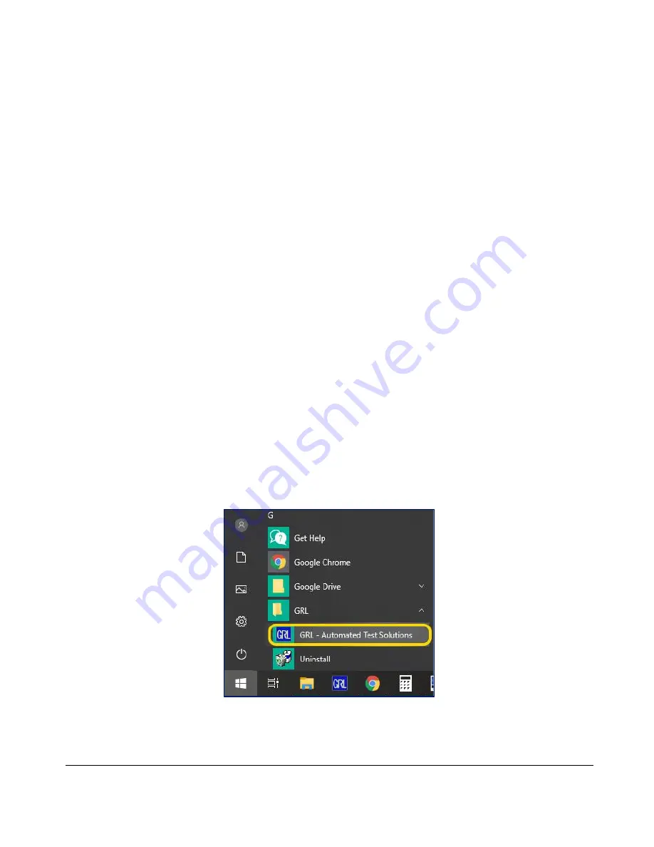
4.


Once the GRL-PCIE-TX software is installed, open the GRL folder from the Windows Start 
menu. Click on 

GRL 

 Automated Test Solutions

 within the GRL folder to launch the GRL 

software framework. 


F

IGURE 

1.


S

ELECT AND 

L

AUNCH 

GRL


F

RAMEWORK


Содержание Express GRL-PCIE-TX

Страница 1: ...CIE TX PCI Express 5 0 Transmitter Compliance Test Automation Solution Quick Start User Guide Method of Implementation MOI for PCIe Gen5 Physical Layer Transmitter Test Application Published on 26 March 2022 ...

Страница 2: ... purpose or any warranty otherwise arising out of any proposal specification or sample The PCI SIG disclaims all liability for infringement of proprietary rights relating to use of information in this specification No license express or implied by estoppel or otherwise to any intellectual property rights is granted herein All product names are trademarks registered trademarks or service marks of t...

Страница 3: ...4 4 2 SET UP DUT TX TEST WITH AUTOMATION 14 4 2 1 Connect Equipment for System Board DUT Test 15 4 2 2 Connect Equipment for Add In Card DUT Test 16 4 2 3 Connect Equipment for System Ref Clock Jitter Test 19 4 2 4 Set Up Test Requirements 20 4 2 5 Select Compliance Tests 22 4 2 6 Configure Test Parameters 25 4 3 RUN AUTOMATION TESTS 27 5 INTERPRETING GRL PCIE TX TEST REPORT 28 5 1 UNDERSTAND TEST...

Страница 4: ...T 39 7 4 ADD IN CARD TX PRESET TEST 39 7 5 SYSTEM BOARD TX BASE JITTER UPW TJ UPW DJDD UTJ AND UDJDD TEST 41 7 6 ADD IN CARD TX BASE JITTER UPW TJ UPW DJDD UTJ AND UDJDD TEST 42 7 7 SYSTEM BOARD REF CLOCK 100 MHZ JITTER TEST 44 8 APPENDIX B CONNECTING KEYSIGHT OSCILLOSCOPE TO PC 45 9 APPENDIX C CONNECTING TEKTRONIX OSCILLOSCOPE TO PC 46 ...

Страница 5: ...ice under test DUT for Tx electrical compliance The GRL P1 hardware controller is designed to work primarily with the software to provide compliance toggle to control the state of the DUT Alternatively an arbitrary function generator can also be used as a secondary option for compliance toggle control The GRL test solution also extends support for RF switch integration to automate switching or sel...

Страница 6: ...IG Compliance Load Board CLB 1 For add in cards For hosts Computer laptop or desktop 1 Windows 7 OS For automation control of the DUT state a Oscilloscope with scope software requirements as specified in vendor specific MOI s For example when using the Keysight Scope scope software such as Keysight InfiniiSim EZ JIT Serial Data Analysis Serial Data Equalization that are required for testing and si...

Страница 7: ...tomation www graniteriverlabs com VISA Virtual Instrument Software Architecture API Software VISA Software is required to be installed on the controller PC running GRL GRL PCIE TX software GRL s software framework has been tested to work with all three versions of VISA available on the Market 1 NI VISA http www ni com download ni visa 17 0 6646 en 2 Keysight IO Libraries www keysight com Search on...

Страница 8: ...ftware as follows 1 If the GRL PCIE TX software is to be installed on a PC where is referred to as controller PC install VISA Virtual Instrument Software Architecture on to the PC where the GRL software is to be used see Section 2 2 2 Download the software ZIP file package from the Granite River Labs support site 3 The ZIP file contains PCIETxTestApplicationxxxxxxxxxxxxSetup exe Run this on the PC...

Страница 9: ... that your license has expired FIGURE 2 START PCIE TX TEST APPLICATION 6 To enable license go to License License Details FIGURE 3 SEE LICENSE DETAILS a Check the license status for the installed application FIGURE 4 CHECK LICENSE FOR INSTALLED APPLICATIONS b Activate a License If you have an Activation Key enter it in the field provided and select Activate If you do not have an Activation Key sele...

Страница 10: ...network addresses for all the connected instruments from the device settings These addresses will be used to connect the instruments to the GRL automation software 12 If using the GRL P1 hardware controller connect the controller via USB to the GRL automation control enabled Scope or PC 13 On the Scope or PC obtain the network address for the connected GRL P1 from the device settings For example i...

Страница 11: ...the information as required for the test session that is currently being run The information provided will be included in the test report generated by the software once tests are completed The fields under DUT Info and Test Info are defined by the user The Software Info field is automatically populated by the software FIGURE 6 SESSION INFO PAGE 3 3 2 Set Test Conditions Select from the menu to acc...

Страница 12: ... 2022 Version 1 0 Mar 2022 Updated 03 26 2022 Page 12 FIGURE 7 SELECT LANE UNDER TEST b Data Rate tab Select the desired PCIe data rates for testing FIGURE 8 SELECT DATA RATES c Preset tab Select the pre defined Tx presets as required for Tx equalization ...

Страница 13: ...GRL PCIE TX Quick Start User Guide MOI Rev1 0 PCI SIG 2022 Version 1 0 Mar 2022 Updated 03 26 2022 Page 13 FIGURE 9 SELECT PRESETS ...

Страница 14: ...ved as a waveform file which is then measured for stress tolerance and preset test compliance In between an optional RF switch can be used and controlled by the GRL PCIE TX software to automate selection of the lane under test When testing is completed the software will generate a test report detailing all results from all lanes tested 4 1 GRL PCIE TX Advantage The GRL PCIE TX test solution provid...

Страница 15: ...owing diagrams describe how to connect the equipment if using GRL P1 with the PCIe Gen5 Compliance Load Board CLB Note the use of GRL P1 in the setup is optional 4 2 1 1 1 PCIe Gen5 System Board Connection Setup FIGURE 10 CONCEPTUAL PCIE GEN5 SYSTEM BOARD TX TEST SETUP DIAGRAM USING GRL P1 1 Insert the CLB into the designated slot on the DUT 2 Connect the Tx Data Lane from the CLB to Channel 1 of ...

Страница 16: ...PCIE GEN5 SYSTEM BOARD TX TEST SETUP DIAGRAM USING GRL P1 WITH ISI 4 2 2 Connect Equipment for Add In Card DUT Test The following connection diagrams show the recommended equipment setups to perform waveform acquisition and analysis for the PCIe Add In Card DUT using a GRL automation control enabled Scope and test controller method 4 2 2 1 Setup Using GRL P1 Hardware Controller with PCIe Test Fixt...

Страница 17: ...ta Lane from the CBB to Channel 1 of the Scope 3 Connect the Tx Data Lane from the CBB to Channel 3 of the Scope 4 Connect the Rx Lane from the CBB to the GRL P1 Output 1 5 Connect the Rx Lane from the CBB to the GRL P1 Output 2 6 Connect the power control adapter cable from the ATX power supply to the CBB 7 Connect the GRL P1 s power control only cable to the input of the power control adapter ca...

Страница 18: ...GRL PCIE TX Quick Start User Guide MOI Rev1 0 PCI SIG 2022 Version 1 0 Mar 2022 Updated 03 26 2022 Page 18 FIGURE 13 CONCEPTUAL PCIE GEN5 ADD IN CARD TX TEST SETUP DIAGRAM USING GRL P1 WITH ISI ...

Страница 19: ...ipment setup to perform waveform acquisition and analysis for the PCIe Gen5 System Ref Clock Jitter Test FIGURE 14 CONCEPTUAL PCIE GEN5 SYSTEM REF CLOCK JITTER TEST SETUP DIAGRAM 1 Insert the CLB into the designated slot on the DUT 2 Connect Ref Clk from the CLB to Channel 1 of the Scope 3 Connect Ref Clk from the CLB to Channel 3 of the Scope 1 Connect the power control adapter cable from the ATX...

Страница 20: ... M 2 fixture connector as supported by the DUT FIGURE 15 SELECT DUT TYPE FIGURE 16 SELECT DUT FIXTURE CONNECTOR TYPE b SigTest Settings tab PCIE Gen1 2 5Gb s Gen2 5Gb s and Gen3 8Gb s Select to run either the pre defined Version 3 2 0 3 or a Custom Version of the SigTest If Custom is selected enter the Version number of the Custom SigTest and also make sure that the SigTest is already installed in...

Страница 21: ...E SETTINGS FOR SYSTEM REF CLOCK JITTER TEST d Waveform Process tab Select Live Capture to acquire PCIe waveforms by the GRL software or select Process Pre captured waveforms to use existing waveforms that have been previously captured and saved for analysis Note that selecting Process Pre captured waveforms will remove the Waveform Acquisition group from the Select Tests page See Section 4 2 5 1 I...

Страница 22: ...nd access all tests available for the selected DUT type User can select any of these tests to perform DUT compliance testing for all PCIe parameters Note The Select Tests page will only list DUT specific tests For example if System Board is selected as the DUT only those tests applicable for System Board will be shown Other test parameters such as desired data rates and presets that were previousl...

Страница 23: ...ysis Note Waveform Acquisition can only be selected if Live Capture is set under the Waveform Process tab on the Setup Configuration page See Section 4 2 4 FIGURE 21 SELECT WAVEFORM TO CAPTURE FOR SYSTEM BOARD FIGURE 22 SELECT WAVEFORM TO CAPTURE FOR ADD IN CARD 4 2 5 2 Select Waveform Analysis Tests Under Waveform Analysis select to perform the SigTest analysis jitter and eye measurements and pre...

Страница 24: ...X Quick Start User Guide MOI Rev1 0 PCI SIG 2022 Version 1 0 Mar 2022 Updated 03 26 2022 Page 24 FIGURE 23 SELECT WAVEFORM ANALYSIS TESTS FOR SYSTEM BOARD FIGURE 24 SELECT WAVEFORM ANALYSIS TESTS FOR ADD IN CARD ...

Страница 25: ... 25 TEST PARAMETERS CONFIGURATION PAGE TABLE 4 TEST PARAMETERS DESCRIPTION Parameter Description Maximum Data Rate Select the highest level for the PCIe data rate to perform tests Show Gen4 Alternate Method Select True to enable the alternate method of performing PCIe Gen4 System Signal Quality test where the Data and 100 MHz Reference Clock can be captured and post processed separately Toggle Con...

Страница 26: ...it Time After Reset ms If Auto Reset has been enabled for the controller specify the time interval in milliseconds to stand by after reset Gen4 System AIC Embedding File If Gen4 Apply Embedding has been set to True enter the name of the file to be used for embedding of the PCIe Gen4 system board or add in card Gen5 System AIC Embedding File If Gen5 Apply Embedding has been set to True enter the na...

Страница 27: ...runs the selected tests when initiated Before running the tests select the option to Skip Test if Result Exists If results from previous tests exist the software will skip those tests Replace if Result Exists If results from previous tests exist the software will replace those tests with new results FIGURE 26 RUN TESTS PAGE Select the Run Tests button to start running the selected tests The connec...

Страница 28: ...f the results are not desired they can be individually deleted by selecting the Delete button Also select the Generate report button to generate a detailed test report in the PDF format FIGURE 27 TEST REPORT PAGE 5 1 Understand Test Report Information This section gives a general overview of the test report to help users familiarize themselves with the format Select the Generate report button to g...

Страница 29: ...9 5 1 2 Test Summary Table This table provides an overall view of all the tests performed along with their test conditions and results FIGURE 29 TEST SUMMARY TABLE EXAMPLE 5 1 3 Test Results This portion displays the results of each test performed in detail along with supporting data points and screenshots ...

Страница 30: ...GRL PCIE TX Quick Start User Guide MOI Rev1 0 PCI SIG 2022 Version 1 0 Mar 2022 Updated 03 26 2022 Page 30 ...

Страница 31: ...GRL PCIE TX Quick Start User Guide MOI Rev1 0 PCI SIG 2022 Version 1 0 Mar 2022 Updated 03 26 2022 Page 31 ...

Страница 32: ... PCI SIG 2022 Version 1 0 Mar 2022 Updated 03 26 2022 Page 32 FIGURE 30 TEST RESULTS EXAMPLE 5 2 Delete Test Results Select the Delete button to delete individual test results or Delete All to delete all test results FIGURE 31 DELETE TEST RESULTS ...

Страница 33: ...he user can switch between different sessions by saving and loading them when needed To save a test session with all of the test parameter information test results and any waveforms select the Options drop down menu and then select Save Session To load a test session back into the application including the saved test parameter settings select Options Load Session To create a new test session and r...

Страница 34: ...Base Jitter UPW TJ UPW DJDD UTJ and UDJDD compliance 2 0M UI acquisition and post processing of acquired waveforms with SigTest Phoenix for o UPW TJ 6 25 ps o UPW DJDD 2 5 ps o UTJ 6 25 ps o UDJDD 3 125 ps 7 1 System Board Tx Signal Quality Test Note Make sure to terminate lanes that are not being tested with 50 ohm MMPX terminators 1 Set up the test equipment as described in Section 4 2 1 2 Adjus...

Страница 35: ...form files in SigTest Phoenix by selecting PCIe 5_0 System Browse Load and Verify Data Make sure the file contains the appropriate trace loss and package model losses embedded with the captured waveform as well as both data and clock 7 Measure both the Eye Height and Eye Width 1e 12 on SigTest Phoenix using the PCIe 5_0 System Optimize_CTLE template file ...

Страница 36: ...1 0 PCI SIG 2022 Version 1 0 Mar 2022 Updated 03 26 2022 Page 36 8 Make sure that each DUT test lane achieves the following target Eye Height and Eye Width values for at least one Tx EQ Preset Eye Width 9 688 ps 0 5 ps Eye Height 17 5 mV 1 5 mV ...

Страница 37: ...lues Tx Signal Quality in the PCI Express Architecture PHY Test Specification Revision 5 0 Version 0 9 to determine the target loss and locate the S4P file to be embedded on the Scope 5 Push the compliance toggle on the DUT to transmit 32 GT s compliance pattern by injecting 1 ms pulse of 100 MHz clock signal into Rx Lane 0 6 On the Scope capture 2 0M UI s for any Tx EQ Preset P0 P10 Save the capt...

Страница 38: ...e 38 8 Measure both the Eye Height and Eye Width 1e 12 on SigTest Phoenix using the PCIe 5_0 Card Optimize_CTLE template file 9 Make sure that each DUT test lane achieves the following target Eye Height and Eye Width values for at least one Tx EQ Preset Eye Width 10 625 ps 0 5 ps Eye Height 22 mV 1 5 mV ...

Страница 39: ...fm for Tekscope waveform or bin for Keysight waveform 5 To test the presets load the saved preset files in SigTest Phoenix by selecting PCIe 5_0 PresetTestAC Template No_CTLE Browse and run the preset tests by selecting Test 6 When the preset tests have completed select Exit to save the test results 7 4 Add In Card Tx Preset Test Note Make sure to terminate lanes that are not being tested with 50 ...

Страница 40: ...pdated 03 26 2022 Page 40 wtf waveform format for example wfm for Tekscope waveform or bin for Keysight waveform 6 To test the presets load the saved preset files in SigTest Phoenix by selecting PCIe 5_0 PresetTestAC Template No_CTLE Browse and run the preset tests by selecting Test ...

Страница 41: ... Adjust the Scope to capture 2M UI s with the following configuration Bandwidth 33 GHz Sampling Rate 128 GS s No embedding 3 Push the compliance toggle on the DUT to transmit 32 GT s Jitter Measurement pattern setting 47 on Lane 0 in the PCIe 5 0 Base Specification and COMPAT on adjacent lanes by injecting 1 ms pulse of 100 MHz clock signal into Rx Lane 0 4 On the Scope capture 2 0M UI s and save ...

Страница 42: ...tion 4 2 2 2 Adjust the Scope to capture 2M UI s with the following configuration Bandwidth 33 GHz Sampling Rate 128 GS s No embedding 3 Turn on SSC on the CBB 0 5 SSC down spread 4 Push the compliance toggle on the DUT to transmit 32 GT s Jitter Measurement pattern setting 47 on Lane 0 in the PCIe 5 0 Base Specification and COMPAT on adjacent lanes by injecting 1 ms pulse of 100 MHz clock signal ...

Страница 43: ...er Guide MOI Rev1 0 PCI SIG 2022 Version 1 0 Mar 2022 Updated 03 26 2022 Page 43 8 The test is considered as Pass if the following target jitter parameter values are met UPW TJ 6 25 ps UPW DJDD 2 5 ps UTJ 6 25 ps UDJDD 3 125 ps ...

Страница 44: ...t being tested with 50 ohm MMPX terminators 1 Set up the test equipment as described in Section 4 2 3 2 Adjust the Scope to capture 80K Clock Cycle 80000 10 ns 0 8 ms 3 SSC can be turned ON or OFF depending on the system board DUT 4 Using the Clock Jitter Tool measure the HF RJ RMS Max Phase Jitter as shown in figure below 5 The test is considered as Pass if the HF RJ RMS Max Phase Jitter is 200 f...

Страница 45: ... installed successfully the IO icon will appear in the taskbar notification area of the PC 3 Select the IO icon to launch the Keysight Connection Expert 4 Click Rescan FIGURE 33 KEYSIGHT CONNECTION EXPERT 5 Refresh the system The Keysight Scope is shown on the left pane and the VISA address is shown on the right pane FIGURE 34 OSCILLOSCOPE S VISA ADDRESS 6 When connecting the Keysight Scope to the...

Страница 46: ...ation FIGURE 35 OPENCHOICE INSTRUMENT MANAGER IN START MENU 3 The left Instruments panel on the OpenChoice Instrument Manager will display all connected instruments The functional buttons below the Instruments panel Instrument List Update Search Criteria Instrument Identify and Properties can be used to detect the Scope in case it does not initially appear under Instruments a Instrument List Updat...

Страница 47: ... Then select the Search Criteria function to ensure that LAN connection is enabled and type in the Scope IP address When the Scope shows up in the list select it followed by Search The Scope should then appear on the Instruments panel Select it and access the Instrument Identify function to view the Scope model and serial number as well as the Properties function to view the Scope address 6 On the...

Отзывы: