ICP
FORCE SENSOR OPERATION MANUAL
9
7.0 LOW-FREQUENCY MONITORING
Force sensors used for applications in short term, steady state
monitoring, such as sensor calibration, or short term, quasi-
static testing should be powered by signal conditioners that
operate in DC-coupled mode. PCB Series 482 and 484 Signal
Conditioner operates in either AC or DC-coupled mode and
may be supplied with gain features or a zero
“
clamped
”
output
often necessary in repetitive, positive polarity pulse train
applications.
If you wish to learn more about ICP
sensors, consult PCB
’
s
General Signal Conditioning Guide, a brochure outlining the
technical specifics associated with piezoelectric sensorsThis
brochure
is
available
from
PCB’s
website
at:
http://www.pcb.com/techsupport/tech_signal
request, free of charge.
8.0 DISCHARGE TIME CONSTANT
The discharge time constant (DTC) of the entire transduction
system from sensor to readout must be considered when
attempting to calibrate an ICP force sensor by static methods.
In order to take full advantage of the long DTC built into the
force sensor, it is best to DC couple from the sensor to the
readout device. Several dual-mode PCB signal conditioners
(e.g., Series 484) use direct coupling techniques to decouple the
output signal from the sensor bias voltage. With the output of
the signal conditioner coupled to a DC readout, such as a digital
voltmeter (DVM) or oscilloscope, the time constant of the
sensor is not compromised by AC coupling elsewhere within
the system.
When DC coupling is required to maximize a sensors DTC in
low frequency applications, it is important to DC couple the
entire system, not just from the sensor to the signal conditioner.
The system time constant is determined by the shortest time
constant in the system. For this reason, the readout device as
well as the signal conditioner must be DC coupled.
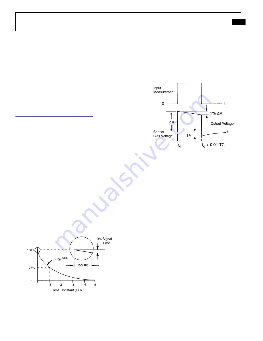
Figure 16 - Characteristic Discharge Time Constant Curve
The discharge time constant represents the decay rate of an
input signal. One DTC represents the amount of time taken for
the signal to decay to 37% of the initial peak value. As
illustrated in
Figure 16
, this is an exponential decay.
Approximately five DTC intervals are needed for a peak signal
to naturally decay back to zero.
The rule of thumb for signal discharge, as outlined in
Figure
17
, is this: for the first 10% of the DTC, the signal lost is
approximately proportional to the time elapsed.
Figure 17 - Step Function Response
Step Function Response
For example, a sensor with a 500-second DTC loses
approximately 1% of its output level the first five seconds (1%
of 500) after the application of a steady state force within the
measuring range. In this case, the output reading must be taken
within five seconds of the force application for 1% accuracy. If
it is impossible to avoid AC coupling somewhere in the sensing
system, try to keep the coupling DTC at least an order of
magnitude longer than the DTC of the force sensor. This avoids
compromising the sensor DTC.
9.0 CALIBRATION
A NIST (National Institute of Standards and Technology)
traceable calibration graph is supplied with each force sensor
certifying its voltage sensitivity (mV/lb). Calibration
procedures follow accepted guidelines as recommended by
ANSI
(American
National
Standards
Institute),
ISA
(Instrument Society of America), and ISO (International
Organization for Standardization). These standards provide the
establishment and management of complete calibration
systems, thus controlling the accuracy of a sensor
’
s
specifications by controlling measuring and test equipment
accuracy. PCB is A2LA accredited for technical competence in
the field of calibration, meeting the requirements of ISO/IEC
17025-1999 and ANSI/NCSL 2540-1-1994.
Содержание 208A11
Страница 17: ......


