30
A04128
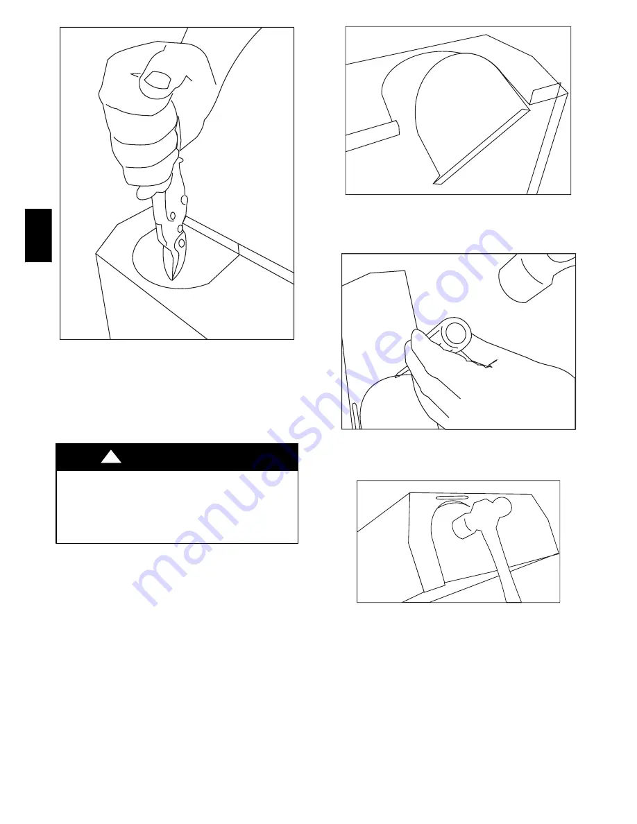
Fig. 29
---
Rounded End of Knockout
For the knockouts in the other locations on the door (top and
sides), tin snips can also be used along the door edges; however,
the preferred method is to use a hammer and screwdriver to strike
a sharp blow (See Fig. 31.) directly to the knockout tie points or
use a hammer in the upper left corner of the desired knockout.
(See Fig. 32.) Remove all burrs and sharp edges.
BURN HAZARD
Failure to follow this caution may cause personal injury.
Hot vent pipe is within reach of small children when
installed in downflow position.
See the following instruction.
CAUTION
!
An accessory Vent Guard Kit, KGAVG0101DFG is REQUIRED
for downflow applications for use where the vent exits through
the lower portion of the furnace casing door. Refer to the Vent
Guard Kit Instructions for complete details.
The horizontal portion of the venting system shall slope upwards
not less than 1/4--in. per linear ft. (21 mm/m) from the furnace to
the vent and shall be rigidly supported every 5 ft. or less with
metal hangers or straps to ensure there is no movement after
installation.
SIDEWALL VENTING
This furnace is not approved for direct sidewall horizontal
venting.
In the U.S.:
Per section 12.4.3.1 of the NFGC, any listed
mechanical venter may be used, when approved by the authority
having jurisdiction.
In Canada:
Per section 7.24.2 of the NSCNGPIC, any listed
venters may be used, when approved by the authority having
jurisdiction. Select the listed mechanical venter to match the Btuh
input of the furnace being vented. Follow all manufacturer’s
installation requirements for venting and termination included
with the listed mechanical venter.
A04129
Fig. 30
---
Knockout Pulled Loose
A04130
Fig. 31
---
Hammer and Screwdriver Used for Knockout
A04131
Fig. 32
---
Remove Knockout with Hammer
PG
8J
/M
Содержание PG8J
Страница 36: ...36 A08411 Fig 46 Wiring Diagram PG8J M ...


