12
Boost ventilation mode with external boost ventilation key
Boost ventilation keys are usually installed in rooms from which air is extracted, such as bathrooms, toilets or
kitchens. In this way, maximum ventilation can be activated locally within these rooms for a specific period to enable
rapid extraction of high humidity and odours. When this control module is activated, the functional features and
displays described for boost ventilation mode apply. Boost ventilation mode is restarted each time it is activated and
interrupts the currently set air volume flow. Afterwards, the unit reverts to the previously active working condition.
Maintenance by the user
For the user, maintenance of the ventilation unit and system is limited to replacing the filters periodically and cleaning
the supply and extract air valves. The filters should be inspected every three months. Filter replacement should be
carried out as necessary, but no later than once every six months. As part of this process, please inspect the other
filters in the ventilation system and replace them if necessary. The filter mats on the extract air valves (e.g. bathroom,
kitchen, WC) should be replaced or cleaned every 2–3 months or when checking the degree of contamination at
one's own discretion.
If the maintenance work is not carried out regularly, this will affect the functionality of the comfort
ventilation system in the long run!
Replacing the unit filters
The system must not be operated without filters. During filter replacement and maintenance work,
the ventilation unit must remain switched off!
Two high-quality original filters from the manufacturer are installed in the FOCUS unit. The filters must be inspected
whenever the control panel signals that this is necessary. In doing so, proceed as follows:
1. Disconnect the unit from the mains power supply.
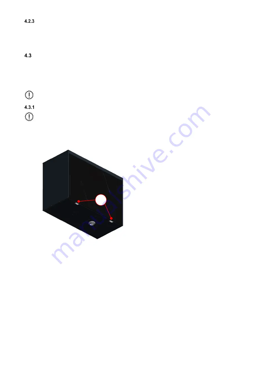
2. Press the two snap fasteners
A
on the bottom of the unit.
Fig. 3: Pressing the snap fasteners
3. Remove the front panel
B
gradually as indicated by the arrows. To do this, open the front panel in the snap
fastener area at an angle of no more than 15° and unhook it from the lock seam of the housing.
A
Содержание FOCUS 200 Base
Страница 1: ...Translation of the original instruction manual Heat Recovery Unit FOCUS 200 Base...
Страница 30: ...30 Dimensions Fig 33 Dimensional drawing...
Страница 31: ...31 FOCUS 200 Base terminal scheme Fig 34 Terminal assignment terminal plan...
Страница 36: ...36 PDE Manual_Focus 200 Base_V1 1 V1122 DE Subject to change...


