11
Touch key
Extract air mode
Pressing this key so that it clicks into place activates extract air mode and switches on
the exhaust air fan. Pressing it again deactivates extract air mode.
If the ventilation unit is being operated together with a
fireplace, do not use this touch key unless supply air mode
is activated at the same time! Simultaneous operation of a
ventilation system and fireplace imposes more stringent safety
requirements with regard to low pressure monitoring and a switch-
off function is required for the ventilation unit.
Touch key
Supply air mode
Pressing this key so that it clicks into place activates the supply air mode and switches
on the supply air fan. Pressing it again deactivates the supply air mode.
Normal mode
Pressing both keys so that they click into place switches on both fans.
Key
Boost ventilation
mode/reset filter
running time
Function key for boost ventilation mode:
Pressing this key activates boost ventilation for 15 minutes with an air volume flow
corresponding to the rotary knob being turned all the way to the right. At the end of the
15-minute boost ventilation time, the unit reverts to the previous air volume in the
currently active mode. You can cancel the boost ventilation mode at any time by
pressing this key again for > 3 s.
Function key for reset filter running time:
To ensure cyclic filter inspection, the control has an integrated operating hours counter
with a fixed running time of 180 d. The boost ventilation mode/reset filter running time
key allows you to reset the filter running time. To restart the filter running time, press
and hold this key for > 3 s.
If the filter running time is reset before the end of 180 d by pressing this key for > 3 s,
the LED fan symbol will blink rapidly four times in succession to confirm the reset
operation.
No reset command can be issued while boost ventilation mode is active!
Table 2: External control panel operating functions
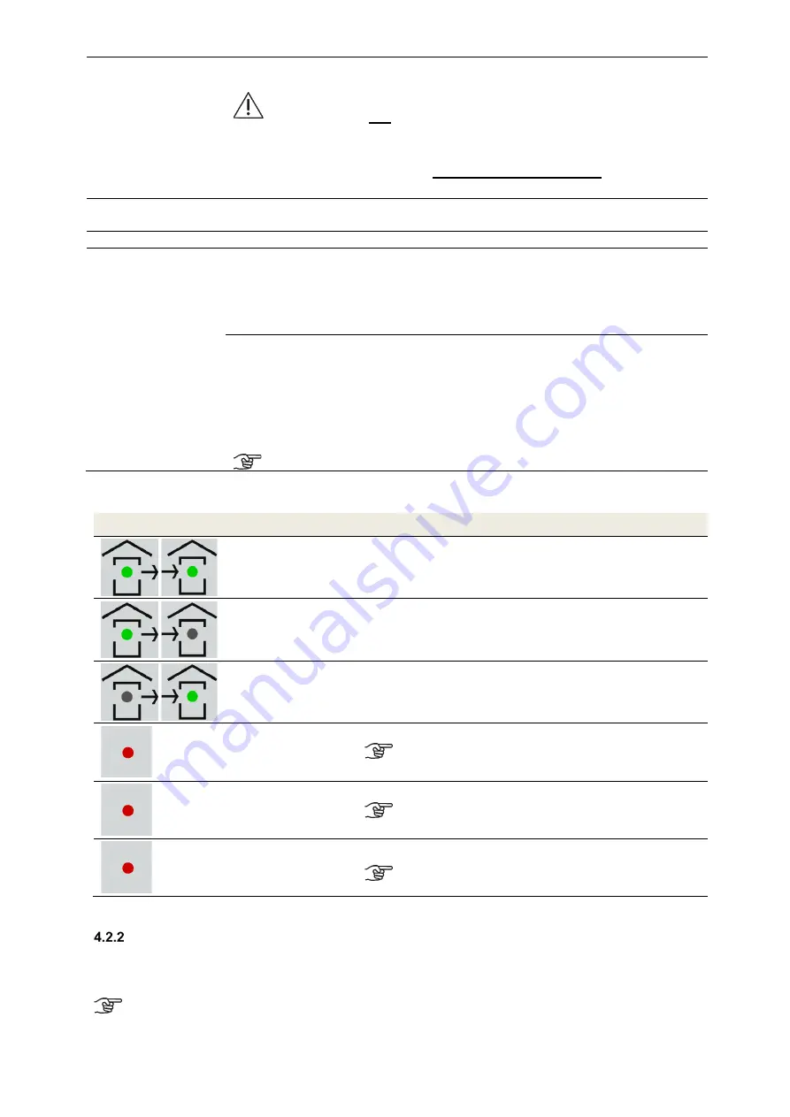
4.2.1.2 Signals used to indicate working/maintenance conditions
Symbol
LED signal
Function / Meaning / Action required
Both LEDs light up
Normal mode (extract air and supply air)
Extract air symbol
LED lights up
Extract air mode is active (extract air only)
Supply air symbol
LED lights up
Supply air mode is active (supply air only)
Fan symbol
LED lights up
Ventilation boost mode is active
The boost ventilation mode
can be selected while in
any other mode!
Fan symbol
LED blinks
Un-occupied mode is active
Un-occupied mode
can be selected while in any
other mode!
Fan symbol
LED blinks rapidly
Filter running time has expired; inspect or replace filter
Boost ventilation mode cannot be activated until a
reset command is
issued!
Table 3: Functions assigned to LED signals
External control signal 0
–
10 V
The ventilation unit can be operated with an external 0–10 V control signal. When a 0–10 V analogue signal is
applied, it is interpreted as a control signal for the fan speed. The current position of the rotary knob on the scale
marks the point at which the external control voltage becomes effective.
To make use of the entire external 0–10 V control range, the rotary knob must be pointing to the
position of the 3rd scaling segment!
Содержание FOCUS 200 Base
Страница 1: ...Translation of the original instruction manual Heat Recovery Unit FOCUS 200 Base...
Страница 30: ...30 Dimensions Fig 33 Dimensional drawing...
Страница 31: ...31 FOCUS 200 Base terminal scheme Fig 34 Terminal assignment terminal plan...
Страница 36: ...36 PDE Manual_Focus 200 Base_V1 1 V1122 DE Subject to change...


