10
Available control modules
The FOCUS unit can be operated with the following control modules:
•
External control panel (W x H x D in mm: 71 x 71 x 25)
•
External control signal (0–10 V)
•
External boost ventilation key(s) (as many as required, potential-free)
External control panel
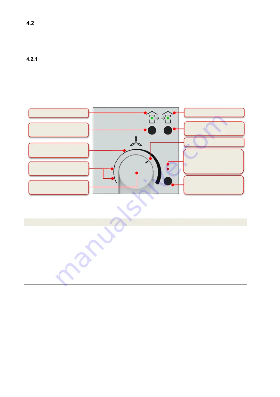
To control the fans, the control panel has a rotary knob with an infinitely variable adjustment range (first scaling
segment on the intensity scale) for the air volume flow.
The two ON/OFF keys can be used to set the operating mode. You can choose between normal mode (both fans
switched on), extract air mode (only the exhaust air fan switched on) or supply air mode (only the supply fan switched
on). The green LED above the respective symbol indicates which mode has been set. Use the boost ventilation
mode/reset filter running time key to trigger the operating function associated with each one. The operating LED
lights up red to indicate that the un-occupied or boost ventilation operating modes are possibly active or that the
filters should be inspected.
4.2.1.1 Control panel operating functions
Description
Explanation
Intensity scale
Rotary knob
positioning
Operating mode:
Ventilation with constant air volume flow
according to the intensity
scale
Position 1st scaling segment on the left: lowest air volume flow
Position 1st scaling segment on the far right: highest air volume flow
Positions within the 1st scaling segment: air volume flow proportional to the intensity
scale
Un-occupied mode:
Ventilation with the lowest intermittent air volume flow
Position 2nd scaling segment: 5 minutes ON and 1 minute OFF
Position 3rd scaling segment on the far left: 1 min ON and 5 min OFF
Positions within 2nd and 3rd scaling segment: ON/OFF cycle-time ratio adapted indirectly
proportional
Fig. 2: Operation and information fields control panel
Function LED red
un-occupied mode/boost ventilation
mode/filter control
Filter control
ON/OFF touch keys
Supply air mode
Intensity scale operating mode
1st scaling segment
ON/OFF touch keys
Extract air mode
Rotary knob for adjusting the air
volume flow
Functional key
Boost ventilation mode/reset filter
running time
Extract air symbol with green LED
Supply air symbol with green LED
Current position of rotary knob
Intensity scale for un-occupied
mode 2nd and 3rd scaling segment
Содержание FOCUS 200 Base
Страница 1: ...Translation of the original instruction manual Heat Recovery Unit FOCUS 200 Base...
Страница 30: ...30 Dimensions Fig 33 Dimensional drawing...
Страница 31: ...31 FOCUS 200 Base terminal scheme Fig 34 Terminal assignment terminal plan...
Страница 36: ...36 PDE Manual_Focus 200 Base_V1 1 V1122 DE Subject to change...


