background image

6

SmartNode 10200 Series Quick Start Guide

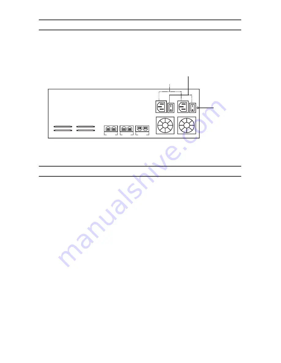
5.0  Connecting to the power source

   1.

Connect to two independent power sources (if only one power source is used, press the green button at 
the rear of the unit to disable the audible alarm). 

   2.

Verify that the Power LED on the front panel is a Solid Green.

Figure 6. 

Connecting the power source

6.0  Connecting to the Control host

   1.

Connect to the Control host through the console serial port (see 

6.1 “Connecting the console serial 

port” 

on page 7) OR the Ethernet management interface (see 

6.2 “Connecting the Ethernet man-

agement interface” 

on page 7). 

The IP address of the management port is 

192.168.200.10/24

. If it is not possible to connect to the 

management port via IP, use the serial cable to connect to the SmartNode Control host for the first time. 

   2.

Default HOSTNAME is the Control host serial number, which can be found in the “Important Notice” sheet 
included with your shipment. 

   3.

Refer to the "Important Notice" sheet for the username and password to log onto the Control host. Navi-
gate to: HTTP://HOSTNAME:12358, to configure the SmartNode unit. (username/password: root/root) 

ETH

VoIP

SMP

0/0 0/1

0/0 0/1

0/0 0/1

Audible

alarm button

Power switch

Power socket

49-64

33-48

17-32

1-16

Содержание SmartNode 10200 Series

Страница 1: ...Start Guide Important This is a Class A device and is not intended for use in a residential environment Part Number 07MSN10200 QS Rev D Revised May 7 2012 Sales Office 1 301 975 1000 Technical Suppor...

Страница 2: ...s may have hazardous voltages present regardless of whether the device is powered ON or OFF PSTN relates to interfaces such as telephone lines FXS FXO DSL xDSL T1 E1 ISDN Voice etc These are known as...

Страница 3: ...t Guide One SmartNode 10200 Important Notice sheet with unique information for your specific unit To install the SN10200 you will need not included Two AC power cords 19 equipment rack 2 0 Installing...

Страница 4: ...1 and SMS ports SMS 0 0 0 1 are not used when connecting VoIP Figure 2 Connecting the VoIP ports 4 0 Connecting to the PSTN Network 1 Connect the SN10200 to the PSTN using one of the following option...

Страница 5: ...Dual BNC connectors 4 3 Optical Interface OC3 STM 1 Figure 5 Connecting to the PSTN via the optical interface ETH VoIP SMP 0 0 0 1 0 0 0 1 0 0 0 1 T1 E1 SCSI connectors 49 64 33 48 17 32 1 16 ETH VoIP...

Страница 6: ...t interface see 6 2 Connecting the Ethernet man agement interface on page 7 The IP address of the management port is 192 168 200 10 24 If it is not possible to connect to the management port via IP us...

Страница 7: ...ode using the specific credentials included on the Important Notice sheet that shipped with your unit The management port is configured with a static Class C IP address by default Figure 8 Connecting...

Страница 8: ...thernet management port follow the instructions in 6 2 Connecting the Ethernet management interface on page 7 2 To access the SN10200 you must use an SSH connection The password is set at the factory...

Страница 9: ...ct to the Web Portal by typing the following in your address bar http DEVICE HOST NAME 12358 or alternately http DEVICE IP ADDRESS 12358 8 2 Logging on to the Web Portal In order to log on to the Web...

Страница 10: ...cular installation If the equipment causes interference to radio or television reception which can be determined by disconnecting the cables try to correct the interference by one or more of the follo...

Страница 11: ...nline support www patton com E mail support support patton com answered within 1 business day Telephone support Standard 1 301 975 1007 USA Monday Friday 8 00 am to 5 00 pm EST 1300 to 2200 UTC GMT Al...

Страница 12: ...tton Electronics assumes no liability for errors that may appear in this document Trademarks statement The term SmartNode is a trademark of Patton Electronics Company All other trademarks presented in...

Отзывы: