background image

Analog FXS

49

Model 2292 & 2294 Series Getting Started Guide 

C • Cabling

Figure 19. Ethernet straight-through

Analog FXS

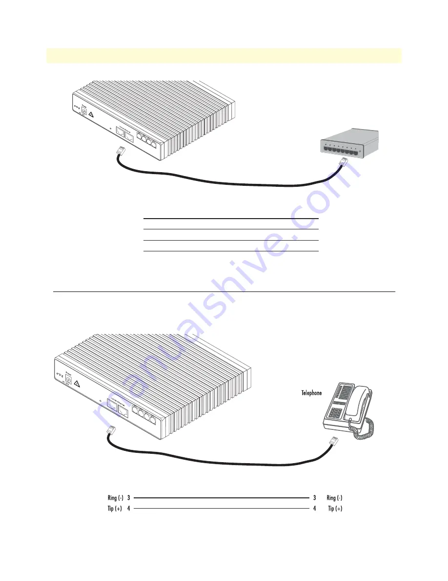
Applicable to SmartNodes equipped with FXS ports. The FXS ports are connected to analog terminals 
(phones, fax machines, answering machines) via cables terminated with RJ-11 connectors (see section 

“Voice 

port”

 on page 51 for details on port pinouts).

Figure 20. Connecting an FXS device

Hub

Straight-through cable

RJ-45, male

Tx+
Tx-
Rx+
Rx-

1
2
3
6

RJ-45, male

1  Rx+
2  Rx-
3  Tx+
6  Tx-

, 1.25A

Reset

Ports

ETH 0/1

ETH 0/0

RJ-11, male

RJ-11, male

, 1.25A

Reset

Ports

ETH 0/1

ETH 0/0

Содержание SmartNode 2292

Страница 1: ...2294 Leased Line Extenders over IP Getting Started Guide Sales Office 1 301 975 1000 Technical Support 1 301 975 1007 E mail support patton com WWW www patton com Part Number 07M2292 GS Rev A Revised April 13 2009 ...

Страница 2: ...s of such license Patton Electronics warrants all SmartNode extender components to be free from defects and will at our option repair or replace the product should it fail within one year from the first date of the shipment This warranty is limited to defects in workmanship or materials and does not cover customer damage abuse or unauthorized modification If the product fails to perform as warrant...

Страница 3: ...ations overview 19 3 Hardware installation 21 4 Getting started with the SmartNode 32 5 LEDs status and monitoring 36 6 Contacting Patton for assistance 38 A Compliance information 41 B Specifications 43 C Cabling 46 D Port pin outs 50 E Installation checklist 52 ...

Страница 4: ...re installation 21 Planning the installation 22 Installation checklist 23 Site log 24 Network information 24 IP related information 24 Software tools 24 Power source 24 Location and mounting requirements 25 Installing the SmartNode extender 25 Mounting the SmartNode extender 25 Connecting cables 25 4 Getting started with the SmartNode 32 Introduction 33 Configure the IP address 34 Power connection...

Страница 5: ...43 Capacity 44 Audio connectivity 44 Data Services 44 Quality of Service 44 Voice Signaling 44 Voice Processing 45 Management 45 System 45 Temperature 45 Humidity 45 C Cabling 46 Introduction 47 Serial console 47 Ethernet 10Base T and 100Base T 48 Analog FXS 49 D Port pin outs 50 Introduction 51 Console port 51 Ethernet 10Base T and 100Base T port 51 Voice port 51 E Installation checklist 52 Intro...

Страница 6: ...6 8 Analog connection 27 9 RJ 11 pinout diagram 27 10 Connecting a SmartNode 2294 Series device to a hub 28 11 Connecting to a host 29 12 Power connector location on rear panel 30 13 SmartNode extender front panel LEDs and Console port locations SmartNode 2294 shown 31 14 Steps for setting up a new SmartNode 33 15 Connecting to the terminal 34 16 Examples of SmartNode 2292 and 2294 Series front pa...

Страница 7: ...klist 23 4 Sample site log entries 24 5 RJ 11 socket 27 6 Ethernet 10 100Base T RJ 45 port pin outs SmartNode 2294 Series 28 7 Factory default IP address and network mask configuration 34 8 SmartNode LED Indications 37 9 RJ 45 socket 51 10 RJ 11 socket 51 11 Installation checklist 53 ...

Страница 8: ...ck start hardware installation procedures Chapter 4 on page 32 describes getting started with the SmartNode extender Chapter 5 on page 36 contains definitions for the LED status indicators Chapter 6 on page 38 contains information on contacting Patton technical support for assistance Appendix B on page 43 contains specifications for the extenders Appendix C on page 46 provides cable recommendation...

Страница 9: ... and WARNING heading indicate a potential electric shock hazard Strictly follow the warning instructions to avoid injury caused by electric shock The alert symbol and WARNING heading indicate a potential safety hazard Strictly follow the warning instructions to avoid personal injury The shock hazard symbol and CAUTION heading indicate a potential electric shock hazard Strictly follow the instructi...

Страница 10: ...ound The mains outlet that is utilized to power the devise shall be within 10 feet 3 meters of the device shall be easily accessible and pro tected by a circuit breaker Hazardous network voltages are present in WAN ports regardless of whether power to the SmartNode is ON or OFF To avoid electric shock use caution when near WAN ports When detaching cables detach the end away from the SmartNode firs...

Страница 11: ... liquids Electrostatic Discharge ESD can damage equipment and impair electrical circuitry It occurs when electronic printed circuit cards are improperly handled and can result in complete or intermit tent failures Do the following to prevent ESD Always follow ESD prevention procedures when removing and replacing cards Wear an ESD preventive wrist strap ensuring that it makes good skin contact Conn...

Страница 12: ...d italic type Parts of commands which are related to elements already named by the user are in boldface italic font Italicized Futura type Variables for which you supply values are in italic font Futura type Indicates the names of fields or windows Garamond bold type Indicates the names of command buttons that execute an action Angle brackets indicate function and keyboard keys such as SHIFT CTRL ...

Страница 13: ...About this guide Model 2292 2294 Series Getting Started Guide 13 ...

Страница 14: ...14 Chapter 1 General information Chapter contents SmartNode Series Leased Line Extenders overview 15 SmartNode 2292 and 2294 Leased Line Extenders 16 Ports descriptions 17 Reset button behavior 17 ...

Страница 15: ...e and data connectivity Figure 1 SmartNode extender SmartNode 2294 shown The SmartNode 2292 and 2294 Leased Line Extenders equipped with two 10 100Base T Ethernet ports pro vide voice over IP VoIP and Internet telephony plus Internet access routing VPN and firewall functions and extensive Quality of Service QoS functions The SmartNode 2292 and 2294 Leased Line Extenders perform the following major...

Страница 16: ...ode 2292 EUI 2 VoIP leased line channels SmartNode 2294 EUI 4 VoIP leased line channels The port combinations are indicated in the extension of the model code T he following model code conven tions apply The last number in the model code stands for the number of voice ports EUI stands for external universal input power supply see figure 3 For example the model code 2294 EUI describes a SmartNode c...

Страница 17: ...le 2 Rear panel ports Port Location Description 10 100 Ethernet ETH 0 0 ETH 0 1 Rear panel RJ 45 connectors see figure 6 on page 26 that connect the extender to an Ethernet device e g a cable or DSL modem LAN hub or switch Analog voice port Rear panel FXS RJ 11 6 position 4 wire connectors see figure 6 on page 26 that connect the extender with an analog terminal Power Rear panel The gateway is ava...

Страница 18: ...e 4 SmartNode 2292 and 2294 front panels Note For LED descriptions refer to chapter 5 LEDs status and monitor ing on page 36 Model 2294 Link 100M Activity 0 0 0 1 Enet 0 Ports Power Console Leased Line Extender Over IP SmartNode 2292 Run VoIP Link Link 100M Activity Enet 1 Model 2292 Link 100M Activity 0 0 0 1 0 2 0 3 Enet 0 Ports Power Console Leased Line Extender Over IP SmartNode 2294 Run VoIP ...

Страница 19: ...19 Chapter 2 Applications overview Chapter contents Typical application 20 Leased line extension 20 ...

Страница 20: ...leased lines can be transported over a packet based network This essentially ensures that with just Internet access at two locations four leased lines between these two locations can be established Combine this with IP routing VPN Security and Quality of Service for up to 4 transparent voice channels and FAX calls over any IP or PSTN network the 2292 2294 leverages low cost IP services with packet...

Страница 21: ...Network Diagram 24 IP related information 24 Software tools 24 Power source 24 Location and mounting requirements 25 Installing the SmartNode extender 25 Mounting the SmartNode extender 25 Connecting cables 25 Installing an interface cable on the extender s voice ports 26 Installing the Ethernet cable 28 Connecting to external power source 30 ...

Страница 22: ...ined by the applicable local and international regulations Ensure that your site is prop erly prepared before beginning installation Before installing the SmartNode extender device the following tasks should be completed Create a network diagram see section Network information on page 24 Gather IP related information see section IP related information on page 24 for more information Install the ha...

Страница 23: ...checklist in your site log Table 3 Installation checklist Task Verified by Date Network information available recorded in site log Environmental specifications verified Site power voltages verified Installation site pre power check completed Required tools available Additional equipment available All printed documents available SmartWare release build number verified Rack desktop or wall mounting ...

Страница 24: ...Ethernet LAN and WAN ports IP addresses of central H 323 Gatekeeper if used IP addresses of central PSTN Gateway for H 323 and or ISoIP based calls IP addresses of central TFTP Server used for configuration upload and download Software tools You will need a PC or equivalent with a VT 100 emulation program e g HyperTerminal to configure the software on your SmartNode extender Power source If you su...

Страница 25: ...the SmartNode extender Place the extender on a desktop or similar sturdy flat surface that offers easy access to the cables The extender should be installed in a dry environment with sufficient space to allow air circulation for cooling Note For proper ventilation leave at least 2 inches 5 cm to the left right front and rear of the SmartNode extender Connecting cables Installing extender cables ta...

Страница 26: ...of the extender The voice ports are connected to analog devices via cables see figure 7 terminated with RJ 11 connectors see figure 9 and table 5 on page 27 for pin out information Figure 6 Rear view showing location of Ethernet connectors and voice ports SmartNode 2294 shown Figure 7 Analog connection 1 25A Reset Ports ETH 0 1 ETH 0 0 Ethernet connectors Voice ports 1 25A Rese t Ports ETH 0 1 ETH...

Страница 27: ...nect directly to telecom network voltage TNV Table 5 RJ 11 socket Pin Signal 3 Ring 4 Tip RJ 11 male RJ 11 male PSTN wall plate 1 25A Reset Ports ETH 0 1 ETH 0 0 Socket 6 5 4 3 2 1 Plug 1 2 3 4 5 6 L in k 1 0 0 M A c ti v it y 0 0 0 1 0 2 0 3 En et 0 Po rts P o w e r Con so le Lea se d L in e Ext en der Ove r IP Sm artNode 2294 R u n V o IP L in k L in k 1 0 0 M A c ti v it y En et 1 ...

Страница 28: ...nnected to the SmartNode s Ether net ports see table 6 for port pin out listing via a cable terminated with RJ 45 plugs Because the SmartNode 2294 Series does not have the MDX feature a cross over cable is required when connecting SmartNode 2294 Series devices to a host see figure 11 on page 29 Note Pins not listed are not used Figure 10 Connecting a SmartNode 2294 Series device to a hub Table 6 E...

Страница 29: ...del 2292 2294 Series Getting Started Guide 3 Hardware installation Figure 11 Connecting to a host Host Cross over cable RJ 45 male Tx Tx Rx Rx 1 2 3 6 RJ 45 1 TX 2 TX 3 RX 6 RX Twisted pair 1 Twisted pair 2 1 25A Reset Ports ETH 0 1 ETH 0 0 ...

Страница 30: ...rear panel 2 Verify that the AC power cord included with your extender is compatible with local standards If it is not refer to Contacting Patton for assistance on page 38 to find out how to replace it with a compatible power cord 3 Connect the male end of the power cord to an appropriate power outlet The extender power supply automatically adjusts to accept an input voltage from 100 to 240 VAC 50...

Страница 31: ...chapter 4 Getting started with the SmartNode on page 32 Console port Power VoIP Link Enet 0 Link Run Enet 0 Activity Enet 0 100M Enet 1 Link Enet 1 100M Enet 1 Activity Voice Port 0 0 Voice Port 0 1 Voice Port 0 2 Voice Port 0 3 Link 100M Activity 0 0 0 1 0 2 0 3 Power Console Leased Line Extender Over IP SmartNode 2294 Run VoIP Link Link 100M Activity L in k 1 0 0 M A c ti v it y 0 0 0 1 0 2 0 3 ...

Страница 32: ...32 Chapter 4 Getting started with the SmartNode Chapter contents Introduction 33 Configure the IP address 34 Power connection and default configuration 34 Connect with the serial interface 34 Login 35 ...

Страница 33: ...rial interface PC or workstation with VT 100 emulation terminal Ethernet interface ETH0 PC or workstation or VT 100 emulation terminal 2 Modify configuration Internet 3 Load configuration 1 Download configuration example Patton Web server with configuration examples Note You can manually configure the SmartNode You do not have to load a configuration file Li nk 10 0M A ct iv ity 0 0 0 1 0 2 0 3 En...

Страница 34: ...apter and cable see figure 15 between the SmartNode s Console port and a PC or workstation s RS 232 serial interface Activate the terminal emulation program on the PC or workstation that supports the serial interface e g HyperTerm Figure 15 Connecting to the terminal Terminal emulation program settings 9600 baud no parity 8 bit 1 stop bit 1 start bit No flow control Table 7 Factory default IP addr...

Страница 35: ... in the pair Copy nvram a side config startup config Copy running config startup config 4 Follow the same procedure for the other SmartNode 229x device in the pair Copy nvram b side config startup config Copy running config startup config Note The configuration above is only a sample configuration that you may use as an example You should specify your own parameters such as your IP address and oth...

Страница 36: ...36 Chapter 5 LEDs status and monitoring Chapter contents Status LEDs 37 ...

Страница 37: ...ive VoIP connection Off indicates the unit is not configured or registered and has no active VoIP connection Flashing green indicates that the unit is attempting or has failed to associate register Voice port Solid when leased line channel is operational Should not be off or blinking Ethernet each port Link Lit when Ethernet link is up 100M On when 100 Mbps Ethernet is selected Activity Flashes wh...

Страница 38: ...er contents Introduction 39 Contact information 39 Warranty Service and Returned Merchandise Authorizations RMAs 39 Warranty coverage 39 Out of warranty service 39 Returns for credit 39 Return for credit policy 40 RMA numbers 40 Shipping instructions 40 ...

Страница 39: ...ed before ship ment All of our products are backed by a comprehensive warranty program Note If you purchased your equipment from a Patton Electronics reseller ask your reseller how you should proceed with warranty service It is often more con venient for you to work with your local reseller to obtain a replacement Patton services our products no matter how you acquired them Warranty coverage Our p...

Страница 40: ...eting a request on the RMA Request page in the Support section at www patton com By calling 1 301 975 1007 and speaking to a Technical Support Engineer By sending an e mail to returns patton com All returned units must have the RMA number clearly visible on the outside of the shipping container Please use the original packing material that the device came in or pack the unit securely to avoid dama...

Страница 41: ...41 Appendix A Compliance information Chapter contents Compliance 42 EMC 42 Safety 42 CE Declaration of Conformity 42 ...

Страница 42: ...irective 1999 5 EC on the approximation of the laws of the member states relating to Radio and Telecommunication Terminal Equipment and the mutual rec ognition of their conformity The safety advice in the documentation accompanying this product shall be obeyed The conformity to the above directive is indicated by CE sign on the device The signed Declaration of Conformity can be downloaded at www p...

Страница 43: ...Appendix B Specifications Chapter contents Capacity 44 Audio connectivity 44 Data Services 44 Quality of Service 44 Voice Signaling 44 Voice Processing 45 Management 45 System 45 Temperature 45 Humidity 45 ...

Страница 44: ...ent server Packet fragmentation Static firewall NAT NAPT RFC 1631 access control lists DMZ port IPsec IKE AES DES 3DES Encryption Quality of Service Audio priority DownStreamQoS Traffic management shaping and policing IEEE 802 1p TOS DiffServ labeling IEEE 802 1Q VLAN tag insertion deletion simultaneous support of multiple VLANs Voice Signaling H 323v4 SIPv2 B2BUA capable multi instance simultaneo...

Страница 45: ...Web HTTP CLI with local console and remote Telnet access TFTP configuration firmware loading SNMP MIB II and product MIB Secure Mass provisioning for both firmware and unit configuration Built in diagnostic tools trace debug call generator System CPU Motorola MPC875 66MHz Memory 32MB SDRAM 8MB Flash Power 100 240 VAC 50 60Hz Power dissipation 4 8W model dependent Temperature 32 104 F 0 40 C Humidi...

Страница 46: ...46 Appendix C Cabling Chapter contents Introduction 47 Serial console 47 Ethernet 10Base T and 100Base T 48 Analog FXS 49 ...

Страница 47: ...n be connected to a serial terminal over its serial console port as depicted in figure 17 Figure 17 Connecting a serial terminal Note See section Console port on page 51 for console port pin outs Serial Terminal Note A Patton Model 16F 561 RJ45 to DB 9 adapter is included with each SmartNode Series device L in k 1 0 0 M A c ti v it y 0 0 0 1 0 2 0 3 Enet 0 Ports P o w e r Console Leased L in e Ext...

Страница 48: ... cable to a host or a straight cable to a hub See figure 18 host and figure 19 on page 49 hub for the different connections Note The SmartNode 2292 Series is equipped with Auto MDX Ethernet ports Use straight through wired cables for host or hub switch connections Figure 18 Ethernet cross over Host Cross over cable RJ 45 male Tx Tx Rx Rx 1 2 3 6 RJ 45 1 TX 2 TX 3 RX 6 RX Twisted pair 1 Twisted pai...

Страница 49: ...nnected to analog terminals phones fax machines answering machines via cables terminated with RJ 11 connectors see section Voice port on page 51 for details on port pinouts Figure 20 Connecting an FXS device Hub Straight through cable RJ 45 male Tx Tx Rx Rx 1 2 3 6 RJ 45 male 1 Rx 2 Rx 3 Tx 6 Tx 1 25A Reset Ports ETH 0 1 ETH 0 0 RJ 11 male RJ 11 male 1 25A Reset Ports ETH 0 1 ETH 0 0 ...

Страница 50: ...50 Appendix D Port pin outs Chapter contents Introduction 51 Console port 51 Ethernet 10Base T and 100Base T port 51 Voice port 51 ...

Страница 51: ...A 561 RJ 45 8 pin port Note Pins not listed are not used Ethernet 10Base T and 100Base T port Note Pins not listed are not used Voice port The voice ports use an RJ 11 connector with 6 positions The midle two positions 3 and 4 are used according to table 10 Note Pins not listed are not used Table 9 RJ 45 socket Pin Signal 1 TX 2 TX 3 RX 6 RX Table 10 RJ 11 socket Pin Signal 3 Ring 4 Tip ...

Страница 52: ...52 Appendix E Installation checklist Chapter contents Introduction 53 ...

Страница 53: ...site log Table 11 Installation checklist Task Verified by Date Network information available recorded in site log Environmental specifications verified Site power voltages verified Installation site pre power check completed Required tools available Additional equipment available All printed documents available SmartWare release build number verified Rack desktop or wall mounting of chassis comple...

Отзывы: