background image

3 • Configuring the RAS for operation

Model 3125 RAS Getting Started Guide

42

Configuring the RAS with a Web browser

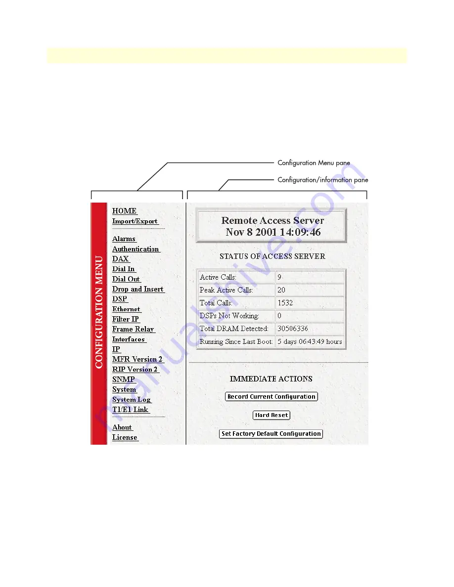
Home page overview

The 

HOME

 window is divided into two panes: the 

Configuration Menu

 pane and the configuration/informa-

tion pane (see figure 23). The 

Configuration Menu

 contains the links to the various RAS subsystems, while the 

configuration/information pane is where you can view status and other information, or make changes to the 
system configuration. Unlike the Configuration Menu pane, which looks the same no matter which subsystem 
page you may move to, the configuration/information pane contents will change as you move from one sub-
system page to another.

Figure 23. HOME page window panes

Содержание ForeFront 3125

Страница 1: ...ard Remote Access Server RAS Getting Started Guide Sales Office 1 301 975 1000 Technical Support 1 301 975 1007 E mail support patton com WWW www patton com Document Number 107172U Rev A Part Number 0...

Страница 2: ...urnished under a license and may be used or copied only in accordance with the terms of such license The information in this document is subject to change without notice Patton Electronics assumes no...

Страница 3: ...1 Introduction 15 Model 3125 Remote Access Server overview 16 Hardware overview 18 WAN 18 LAN 19 Signaling 19 Modems 19 RS 232 control port 19 Power system 19 Central processing unit 19 Temperature 1...

Страница 4: ...Configuring simple authentication 44 No Validation 44 A Static User 45 Configuring dial in user information 46 Configuring the default gateway 48 Configuring line settings and signaling for E1 49 Conf...

Страница 5: ...5 Model 3125 RAS Getting Started Guide Contents Returns for credit 64 Return for credit policy 65 RMA numbers 65 Shipping instructions 65...

Страница 6: ...Contents Model 3125 RAS Getting Started Guide 6...

Страница 7: ...le line individual service may be extended by means of a certified connector assembly telephone extension cord The customer should be aware that compliance with the above condition may not prevent deg...

Страница 8: ...ll select the code it has available The Service Order Code s SOC 6 0Y The required Universal Service Order Code USOC jack RJ 48C The make model number and FCC Registration number of the RAS 2 Your tel...

Страница 9: ...returns must have a Return Materials Authorization number on the outside of the shipping container This number may be obtained from Patton Electronics Technical Service at Tel 301 975 1007 E mail supp...

Страница 10: ...Compliance Information Model 3125 RAS Getting Started Guide 10...

Страница 11: ...is a LAN connected to the Ethernet port of the RAS Audience This guide is intended for the following users Operators Installers Maintenance technicians Structure This guide contains the following cha...

Страница 12: ...ow the warning instructions to avoid personal injury The shock hazard symbol and CAUTION heading indicate a potential electric shock hazard Strictly fol low the instructions to avoid property damage c...

Страница 13: ...is word means to move the mouse in such a way that the tip of the pointing arrow on the screen ends up resting at the desired loca tion Click Means to quickly press and release the left or right mouse...

Страница 14: ...About this guide Model 3125 RAS Getting Started Guide 14...

Страница 15: ...18 WAN 18 LAN 19 Signaling 19 Modems 19 RS 232 control port 19 Power system 19 Central processing unit 19 Temperature 19 Altitude 19 Humidity 19 Physical dimensions 20 3125RC Resource Card 20 3125TM...

Страница 16: ...architecture see figure 2 on page 17 The front blade feature LED indicators for Power CPU Fail Alarm System Ethernet A Ethernet B Calls Act PMC and WAN Port status The rear blade contains the T1 E1 PR...

Страница 17: ...Model 3125 Remote Access Server overview 17 Model 3125 RAS Getting Started Guide 1 Introduction Figure 2 Patton 2U 4U and 6U cPCI platforms...

Страница 18: ...LEDs and control port on the chassis front panel while connections for WAN and LAN are located on the rear 3125 Transition Module Figure 3 Model 3125 RAS features WAN The Model 3125 includes four WAN...

Страница 19: ...provides for initial configuration of the RAS The RS 232 port also supports Asynchronous data at 19 2 kbps An RJ 45 connector with EIA 561 pinout A VT 100 console management interface Hardware CD and...

Страница 20: ...Model 3125 RAS Getting Started Guide 20 Hardware overview Physical dimensions 3125RC Resource Card Weight 0 8 lbs 0 35 kg Refer to figure 4 for height width and depth dimensions Figure 4 3125RC physi...

Страница 21: ...login and password Dual SNMP HTTP passwords for monitor and superuser access levels Packet filtering on dial in user traffic and Ethernet port Management services Out of Band RS 232 configuration por...

Страница 22: ...and control using a standard Web browser Figure 6 3125RC status LEDs LED display The front panel see figure 6 includes LEDs for POWER Green if power is being applied Flashing if a power supply has fai...

Страница 23: ...h of the four T1 E1 PRI links Red indicates an error Approvals The Model 3125 RAS has achieved the following approvals FCC Part 15 Class A FCC Part 15 Class B FCC Part 68 Complies with UL1950 MET Cana...

Страница 24: ...10 second average Online help 802 3 Ethernet ARP RARP IP over Ethernet Proxy ARP for dial up IP addresses PSTN Connectivity T1 CT1 Robbed Bit with Ground Start Loop Start E M Wink E M Immediate Taiwan...

Страница 25: ...Module 27 Installing the 3125RC Resource Card 30 Cable installation 31 Connecting the Ethernet ports 31 Connecting the 10 100Base T Ethernet port to an Ethernet switch or hub 32 Connecting the 10 100...

Страница 26: ...ping carrier immediately for claim purposes Save all packing materials in case you need to return an item to the factory for servicing The 3125 RAS comes with the following items The Model 3125 Series...

Страница 27: ...easily be damaged by electrostatic discharge ESD resulting from the build up of electri cal potential on clothing and other materials To avid damaging the 3125 modules perform the following safety an...

Страница 28: ...n each injection ejection handle to release the handle see figure 7 Figure 7 Releasing a injection ejection handle 5 Locate the slot where the 3125TM will be installed Insert the 3125TM so it enters t...

Страница 29: ...il it engages the mid plane see figure 9 when that hap pens pivot the injection ejection handles into locked position see figure 10 Verify that the red tab in each handle clicks into place indicating...

Страница 30: ...the card cage 2 Remove the 3125RC Resource Card from its anti static bag 3 Press on the red tab on each injection ejection handle to release the handle see figure 7 on page 28 4 Locate the slot where...

Страница 31: ...ing the Ethernet ports The 3125TM has a dual 10 100 Ethernet interface for connection to your LAN see figure 12 The Ethernet port will autosense the correct speed of the local LAN and automatically ne...

Страница 32: ...rt to an Ethernet capable workstation The 10 100Base T Ethernet port can connect to a single Ethernet capable workstation by means of a cross over cable Refer to figure 14 to assemble a cross connect...

Страница 33: ...imary T1 E1 PRI port RJ 48C on the RAS Note For 75 ohm twin coax E1 connections use the Patton Model 460 E1 120 ohm 75 ohm adapter to convert from a 75 ohm dual coax to the 120 ohm twisted pair interf...

Страница 34: ...2 Hardware installation Model 3125 RAS Getting Started Guide 34 Completing the hardware installation...

Страница 35: ...dial in user information 46 Configuring the default gateway 48 Configuring line settings and signaling for E1 49 Configuring the line settings 50 Setting the line signaling for an E1 PRI ISDN line 51...

Страница 36: ...he remote access server s local LAN The IP address and subnet mask for the RAS s Ethernet port A range of IP addresses to be assigned to the dial in users IP pool The IP addresses of the domain name s...

Страница 37: ...Set up HyperTerminal as follows Open a HyperTerminal session Enter a name for this connection Click on the Connect using pop up menu and choose the Direct to ComX option where X is the number of the...

Страница 38: ...ing the RAS for configuration Figure 18 COM properties Figure 19 Terminal keys configuration Configure the Settings for Function arrow and ctrl keys act as to Terminal keys as shown in figure 19 4 Pre...

Страница 39: ...rnet 7 Select a PrimaryIpAddress to set the Ethernet A IP address 8 Type the IP address at the prompt then press RETURN 9 Use the left arrow key to return to the previous menu 10 Select b PrimaryIpMas...

Страница 40: ...RAS or you must configure the default gateway using HyperTermi nal Select i IP then 2 Default Gateway Configuring the RAS with a Web browser This section describes configuring the following User auth...

Страница 41: ...Configuring the RAS with a Web browser 41 Model 3125 RAS Getting Started Guide 3 Configuring the RAS for operation Figure 22 Home page...

Страница 42: ...e 23 The Configuration Menu contains the links to the various RAS subsystems while the configuration information pane is where you can view status and other information or make changes to the system c...

Страница 43: ...buttons Hard Reset this button figure 24 causes the RAS to perform a cold restart When you select Hard Reset the RAS confirms that you want to execute this command Then the RAS will disconnect all cu...

Страница 44: ...g sections describe two methods for configuring simple authentication to test the setup No Validation A No Validation authentication setting means that the user will be able to log in without requirin...

Страница 45: ...uthentication Configuration window appears see figure 26 3 Change Validation to noValidation 0 4 Click on the Submit Query button A Static User The Static User authentication setting means that the us...

Страница 46: ...dd the desired username and password 4 Click on the Submit Query button 5 Click on Modify The Authentication Configuration window appears see figure 26 on page 45 6 Change Validation to StaticUsers 1...

Страница 47: ...first and last host in the block for example 192 49 110 151 155 The addresses can be from a subnet other than the local network the RAS is on The IP address pool can have IP addresses from multiple s...

Страница 48: ...es users to find locations on the Internet 7 Click on Submit Query Configuring the default gateway Do the following to add the default gateway if it was not already configured through HyperTerminal 1...

Страница 49: ...Menu The T1 E1 Link Activity window appears see figure 32 Figure 32 T1 E1 Link Activity window 2 Link 1 corresponds to Line 1 on the RAS This is the primary link for dial in callers Under Link 1 Click...

Страница 50: ...nu see figure 33 on page 49 and select e1pulse 1 4 Click on Yellow Alarm Format pop up menu see figure 33 on page 49 and choose from the following options For an E1 PRI line choose linkYellowFormatDL...

Страница 51: ...l Mode pop up menu and choose messageOriented 4 3 Click on the Message Oriented Switch Type pop up menu see figure 35 and choose CTR4 3 4 Click on Submit Query Signaling is now configured for E1 PRI S...

Страница 52: ...t from the phone company The called Number is the number a user dials to call into the RAS 9 Set the First Middle and Last Response Codes These are the codes the switch expects after each digit sent b...

Страница 53: ...nfiguration Menu The T1 E1 Link Activity window appears see figure 32 on page 49 2 Click on Channel Assignment The WAN Circuit Channel Assignment window appears see figure 37 Figure 37 WAN Circuit Cha...

Страница 54: ...I line Otherwise refer to Setting the line signaling for a robbed bit T1 line Setting the line signaling for an ISDN PRI line Do the following 1 Scroll down the WAN Circuit Configuration window until...

Страница 55: ...4 Click on Submit Query Saving your configuration The basic configuration for the RAS is now finished Do the following to save your configuration settings 1 Select Home on the Configuration Menu The H...

Страница 56: ...e Configuration Menu to display the Import Export main window see figure 38 Figure 38 Import Export main window 5 To export the flash configuration click on the Export Flash link on the Import Export...

Страница 57: ...n This section verifies that the RAS is fully operational 1 Temporarily disconnect the male ends of both power cords from the power outlet Wait 30 seconds then plug the power cords in again 2 Verify t...

Страница 58: ...RAS 10 100 Ethernet port a green LED that indicates line speed and a yellow LED that indicates link status and activity Verify that the yellow LED is either flashing yellow meaning that packets are be...

Страница 59: ...59 Chapter 4 Operation and shutdown Chapter contents Introduction 60 Activating the RAS 60 De activating the RAS 60...

Страница 60: ...for use 4 There are two LEDs on the RAS 10 100 Ethernet port a green LED that indicates line speed and a yellow LED that indicates link status and activity The yellow LED is either flashing yellow me...

Страница 61: ...en the captive fasteners on the 3125TM see figure 11 on page 30 until the fasteners no longer attach the module to the rack 6 Press the red tab on each injection ejection handle to release the handles...

Страница 62: ...4 Operation and shutdown Model 3125 RAS Getting Started Guide 62 De activating the RAS...

Страница 63: ...r contents Introduction 64 Contact information 64 Warranty Service and Returned Merchandise Authorizations RMAs 64 Warranty coverage 64 Out of warranty service 64 Returns for credit 64 Return for cred...

Страница 64: ...ent All of our products are backed by a comprehensive warranty program Note If you purchased your equipment from a Patton Electronics reseller ask your reseller how you should proceed with warranty se...

Страница 65: ...a request on the RMA Request page in the Support section at www patton com By calling 1 301 975 1000 and speaking to a Technical Support Engineer By sending an e mail to returns patton com All return...

Отзывы: