manualshive.com logo in svg
background image

TOOL INSTALLATION

Your Paslode tool comes ready for immediate use
and can be installed by following these steps:
1.  SAFETY - All tool operators and their immediate 
supervisors must become familiar with the operator 
safety instructions before operating the tool.  The 
instructions are on page 2 of this manual.

2.  Included wuth each tool are one copy of this 
Safety and Maintenance manual and one copy of 
the Tool Schematic.  Keep these publications for 
future reference.  An ownership registration card is 
also included.  This card must be completed and 
returned to Paslode immediately to register your 
ownership.

3.  The plastic cap in the air inlet of the tool must be 
removed before the male fitting is installed.  The fit-
ting must be a male pneumatic type that discharges  
the air from the tool when the air line is discon-
nected.

4.  Install a filter/regulator/lubricator unit, with a 
gauge as close as practical to the tool, preferably 
within ten feet.  Refer to the Air Systems section of 
this manual for air hose requirements and lengths.  
In general, no other special installation is required.

5.  If the operator is working at a bench or table, 
it is usually best to run the air line underneath the 
bench.  A small tray under the benchtop can hold 
the fastener supply and the tool when not in use.

6.  If this tool does not work when it is first connect-
ed, do not try to make repairs.  Call your Paslode 
representative immediately.  

TOOL OPERATION

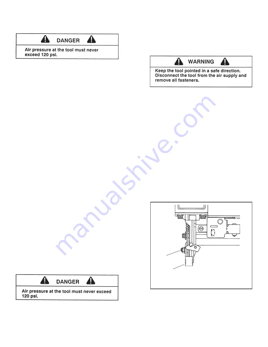
Depth of Drive Adjustment

(On tools equipped with this feature)

The depth of drive adjustment is made by 
adjusting  the work contacting element.  The 
lock nut is loosened to allow the element to be 
moved up or down.  You will need a 3/8 inch 
open end or 5/32 inch hex socket wrench to 
make this adjustment.

If the tool is overdriving (the fastener head or 
crown is driven below the work surface), the 
work contacting element should be moved 
downward.  If the fasteners stand up (the head 
or crown is not flush with the surface), the work 
contacting element should be moved up.

Adjust the work contacting element until the 
fastener head or crown depth meets job re-
quirements.

LOCK 
NUT

WORK 
CONTACTING 
ELEMENT

MOVE UP
TO INCREASE 
DRIVE DEPTH

MOVE DOWN
TO INCREASE 
DRIVE DEPTH

5

Содержание F400S

Страница 1: ...P Operating and Maintenance Manual PNEUMATIC TOOLS 403606 18 08 07...

Страница 2: ...length in inches that can be used with the tool 00 S 00 P Type of tool P powerpack DL double length Gauge of fastener Indicates crown size W wide S standard I intermediate N narrow Maximum fastener l...

Страница 3: ...ur new tool Also read Paslode s warranty statement in the back of this manual Even though Paslode ia a leader in the power fastening business we continually strive to find new and better ways of impro...

Страница 4: ...a safety mechanism called a work contacting element to help prevent accidental firing Never tamper with disable or remove the work contacting element Do not use the tool unless the work contacting el...

Страница 5: ...he bottom of each branch line A refrigerant type dryer is installed on the system Air hoses are kept as short as practical A regular maintenance program is followed Outdoor Air System Installation Be...

Страница 6: ...ed We can use the following example 10 tools X 30 fasteners minute tool X 1 2 X 0 051scfm 100psi 18 36 scfm This number is found in the Air Consumption Chart In this example using the air consumption...

Страница 7: ...ir hose requirements and lengths In general no other special installation is required 5 If the operator is working at a bench or table it is usually best to run the air line underneath the bench A sma...

Страница 8: ...tool trigger to avoid unintentional fastener discharge Sequential Operation Silver Trigger The sequential operating kit prevents succesive or bounce driving Depress the work contacting element and ho...

Страница 9: ...Remove the retainer from a nail coil and place the nail coil in the magazine with the tips of the nails against the loading tray and with about 4 inches of coil unwound Step No 4 Slide the free strip...

Страница 10: ...he nails The tool is now ready for use RHP 350 PowerMaster Plus Strip Nailers Step No 1 Grasp the nailer handle firmly Pull the magazine follower all the way to the rear of the magazine until it is la...

Страница 11: ...ep No 3 When the follower reaches the reload area marked on the side of the magazine you may insert a new strip of nails When the follower arrow reaches the lockout area the tool automatically locks t...

Страница 12: ...the tank will keep the air free of frost Testing the Tool After Servicing After replacing any part or parts it is important to check the tool for proper operation This ensures that the tool was put t...

Страница 13: ...Keep tool lubricated Prevent clogging of filter with dirt Prevent air leakage and pro mote efficient operation Promote operator safety and efficient tool operation Prevent jamming of fasteners Assure...

Страница 14: ...air lines 3 8 inch ID minimum Adjust work contacting element extend length Reduce air pressure Open front guide latch release jammed fastener and close latch securely Check magazine for proper fastene...

Страница 15: ...TOOL WARRANTY TOOL WARRANTY AND LIMITATIONS An Illinois Tool Works Company 888 Forest Edge Drive Vernon Hills Illinois 60061 P 13...

Страница 16: ...P An Illinois Tool Works Company 888 Forest Edge Drive Vernon Hills Illinois 60061 www paslode com Printed in U S A 2007 Illinois Took Works Inc...

Отзывы: