Precision Interferometer
012-07137B
6
®
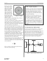
The Fabry-Perot Interferometer
In the Fabry-Perot Interferometer, two partial mirrors are
aligned parallel to one another, forming a reflective cavity.
Figure 4 shows two rays of light entering such a cavity and
reflecting back and forth inside. At each reflection, part of
the beam is transmitted, splitting each incident ray into a
series of rays. Since the transmitted rays are all split from a
single incident ray, they have a constant phase relationship
(assuming a sufficiently coherent light source is used).
The phase relationship between the transmitted rays
depends on the angle at which each ray enters the cavity
and on the distance between the two mirrors. The result is
a circular fringe pattern, similar to the Michelson pattern,
but with fringes that are thinner, brighter, and more widely
spaced. The sharpness of the Fabry-Perot fringes makes it
a valuable tool in high-resolution spectrometry.
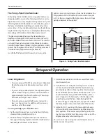
As with the Michelson Interferometer, as the movable
Setup and Operation
Laser Alignment
• If you are using a PASCO Laser and Laser Alignment
Bench, the setup and alignment procedure is as fol-
lows.
• If you are using a different laser, the alignment proce-
dure is similar. Adjust your laser so that the beam is
approximately 4 cm above the table top. Then align
the beam as in steps 4 and 5, below.
• If you are using a spectral light source instead of a
laser, see
Suggestions for Additional Experiments
,
near the end of the manual.
To set up and align your PASCO Laser:
1.
Set the interferometer base on a lab table with the mi-
crometer knob pointing toward you.
2.
Position the laser alignment bench to the left of the
base approximately perpendicular to the interferometer
base and place the laser on the bench.
mirror is moved toward or away from the fixed mirror, the
fringe pattern shifts. When the mirror movement is equal
to 1/2 of the wavelength of the light source, the new fringe
pattern is identical to the original.
3.
Secure the movable mirror in the recessed hole in the
interferometer base.
4.
Turn the laser on. Using the leveling screws on the la-
ser bench, adjust its height until the laser beam is ap-
proximately parallel with the top of the interferometer
base and strikes the movable mirror in the center. (To
check that the beam is parallel with the base, place a
piece of paper in the beam path, with the edge of the
paper flush against the base. Mark the height of the
beam on the paper. Using the piece of paper, check that
the beam height is the same at both ends of the bench.)
5.
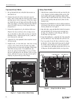
Adjust the X-Y position of the laser until the beam is
reflected from the movable mirror right back into the
laser aperture. This is most easily done by gently slid-
ing the rear end of the laser transverse to the axis of the
alignment bench, as shown in Figure 5.
You are now ready to set up the interferometer in any of
its three modes of operation.
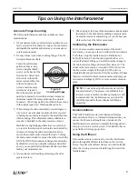
Figure 4. Fabry-Perot Interferometer
Adjustable
Movable
Partial Mirrors
Viewing
Screen
Содержание OS-9255A
Страница 27: ...PrecisionInterferometer 012 07137B 24...


