www.parweld.com
6
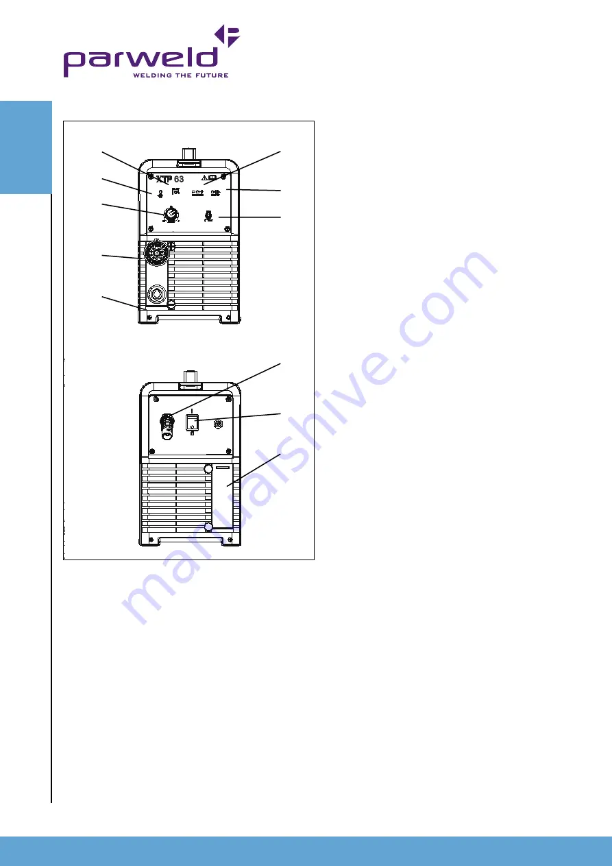
8) Torch connector
9) Earth lead connector.
10) Air line connector
11) Consumable holder
5.0 Installation
Read entire installation section before starting installation.
SaFetY preCautIOnS
• ELECTRIC SHOCK can kill.
• Only qualified personnel should perform this installation.
• Only personnel that have read and understood the Operating
Manual should install and operate this equipment.
• Machine must be grounded per any national, local or other
applicable electrical regulations.
• The power switch is to be in the OFF position when installing
work cable and torch and when connecting other equipment.
5.1 Unpacking the Machine
Carefully remove the machine from the packaging, we recommend
you retain the packaging until the machine has been fully installed
and tested incase it has been damaged in transit and has to be
returned to the re-seller.
5.2 location
Be sure to locate the welder according to the following guidelines:
In areas, free from moisture and dust.
Ambient temperature between 0-40
0
C.
In areas, free from oil, steam and corrosive gases.
In areas, not subjected to abnormal vibration or shock.
In areas not exposed to direct sunlight or rain.
Place at a distance of 12” (300 mm) or more from walls or similar
that could restrict natural airflow for cooling.
5.3 Input and grounding connection
WarnInG
Before starting the installation, check that your power supply
is adequate for the voltage, amperage, phase, and frequency
specified on the Machine nameplate.
Operate the welding power source from a single-phase 50/60 Hz,
AC power supply. The input voltage must match one of the electrical
input voltages shown on the input data label on the unit nameplate.
The XTP-63 machine can be used on 400V supply and will
automatically adjust itself depending upon the voltage applied.
Refer to the specifications table for voltage tolerances.
Have a qualified electrician connect the input plug. For long runs
over 30m , larger copper wires should be used. The green/yellow
wire in the input cable connects to the frame of the machine. This
ensures proper grounding of the machine when the machine plug is
inserted into the receptacle.
4.0 Description of Controls
1) ON OFF Switch for switching on or off the mains supply to the
machine. The switch is mounted on the rear panel.
2) Fault light This indicates a fault or over temperature condition
with the machine refer to the fault finding section for further
information
3) Power light This indicates mains power is applied to the machine
and that the machine is currently switched on when the light is
illuminated
4) Output power control for adjustment of the power output of the
machine between 20 and 60Amps.
5) Interlock fault. If this light illuminates it indicates one of the
following. Short circuit between the electrode and tip, front end torch
parts missing or incorrectly fitted, Shield cup not fitted correctly
(lamp flashes) low air pressure.
6) Output power on. Illuminates when the DC output current is on.
7) Run/Set switch. In the set position the Air can be checked by
pressing the trigger to ensure the air is connected and flowing.
CO
ntr
O
lS
1
10
11
5
6
7
2
3
4
8
9
Содержание XTP-63
Страница 1: ...Operator Manual ISSUE 1 XTP 63...
Страница 13: ...www parweld com 13...


