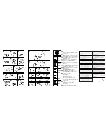
N. REPLACING NYLON LINE
1)
Unscrew the blocking screws at the bottom of the
string head by turning them counter- clockwise.
2)
Remove the base cover assembly.
Remove the empty spool from the housing and
discard any remaining line.
REWINDING NEW LINE
3)
Prepare 2 lengths (8ft each) of 2.4 mm nylon
line. Thread 1 end of each line into the two
holes on opposite sides of the spool. Pinch the
exposed ends flat with a pair of pliers to
prevent them slipping through the hole.
4)
Wind the two lines in the same direction
around the spool.
REASSEMBLY
5)
Slide the end of the two lines into the grooves
to hold the line temporarily.
6)
Position the spool back into the housing and
pull the line through the eyelets.
7)
Pull about 12cm (5ins) of line out on either side.
8)
Reassemble the string head as shown, tighten
the screws clockwise.
9)
N.B: In order to extend the nylon line as it
wears down, pull the mower gauge
downwards and turn it in a clockwise direction
to feed out the desired length of line.
L. CARBURETTOR ADJUSTMENT
Your machine may be fitted with a highly
sensitive low emission carburettor. We now
therefore recommend that carburettor
adjustments are only made by an authorised
servicing dealer, equipped with instruments
that will ensure best performance with lowest
emission levels.
To adjust the idle speed, however, proceed as
follows:
With engine running and warm, slowly turn screw
‘I’ or ‘T’ clockwise until the engine runs smoothly
with a consistent noise level but without making
the chain or cutting head rotate.
If the cutting attachment does move or the engine
runs too fast, slowly turn screw ‘I’ or ‘T’ in an
anticlockwise direction until the correct speed is
obtained.
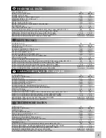
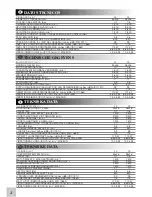
Precise numerical engine speed settings are
mentioned in the technical detail chart in the front
of the owner’s manual.
NOTE:
A)
Direct drive trimmers: The cutting head will
always rotate when engine is running.
B)
All the above mentioned adjustments must be
made with the relevant cutting attachment
correctly fitted.
Warranty may be invalidated from incorrect
carburettor adjustment made by persons
other than an authorised dealer.
From time to time ensure all screws are tight.
Replace damaged, worn, cracked or warped
blades. Always make sure nylon string head or
blade have been assembled correctly (see
sections NYLON STRING HEAD and BLADE
ASSEMBLY) and blade fastener is tightened.
1) AIR FILTER CLEANING
(at least every 25 working hours).
A dust clogged air filter may cause carburetor
problems.
This may prevent the engine from reaching its
maximum speed and cause high fuel
consumption and/or difficult starting.
Remove filter cover as shown in figure 1.
Carefully clean the inside of filter box. The filter
can also be cleaned with compressed air.
2)
Every 50 working hours inject the gearcase with
gear grease under high pressure through hole (C).
3) SPARK PLUG
From time to time (at least every 50 hours)
remove and clean the spark plug and check
the electrode gap (0,5/0,6 mm.). Replace
spark plug about every 100 working hours or
whenever it is extremely encrusted. Heavily
encrusted electrodes can result from an
incorrect carburetor setting or from wrong fuel
mixture (too much oil in the petrol) or a poor
quality of oil in the fuel mix. Check and correct.
4) FUEL FILTER
To change fuel filter remove the tank cap and
pull out the filter with a piece of bent wire or
long forceps. Contact your Service Station for
general servicing and cleaning of internal parts
at least once a year.This will reduce the
possibility of unexpected problems and will
ensure maximum product life and efficiency.
REGULARLY: it is important, in order to avoid
engine overheating, to remove dust and dirt
from slots, gaps and from in between cylinder
fins using a wooden scraper.
LONG STORAGE: empty fuel tank and run
engine until dry.
Store trimmer in a dry place.
M. REGULAR MAINTENANCE
A
10


